Backward Wave Oscillator (BWO)
How a TWT Can Be Used as an Oscillator: Backward-Wave Oscillator
The Traveling Wave Tube (TWT) is normally operated as a wideband microwave amplifier, but the traveling-wave principle can also be used to generate microwave oscillations. A major oscillator belonging to the traveling-wave tube family is the Backward Wave Oscillator (BWO), also known as a carcinotron. Unlike a conventional TWT amplifier, where the RF wave and electron beam interact to produce an amplified signal that travels toward the output, the BWO uses a backward-propagating wave to extract energy continuously from the electron beam and sustain oscillation. The electromagnetic wave has a group velocity directed opposite to the electron-beam motion, and the generated microwave output is coupled out near the electron-gun side of the tube. This arrangement allows the device to operate as a tunable microwave source and can extend into very high-frequency and terahertz applications.
How a TWT-Based Device Behaves as an Oscillator
A conventional TWT amplifier requires an external RF signal at its input. The electron beam supplies energy to this signal through continuous interaction with the slow-wave structure, and the amplified RF signal is extracted at the output end. For oscillator operation, however, the device must generate and sustain an RF signal without requiring a continuous external RF input. The traveling-wave structure and electron beam are therefore arranged so that a wave traveling in the backward direction can interact with the electron beam and receive energy from it. In a Backward Wave Oscillator, the backward wave travels from the collector region toward the electron gun, while the electron beam travels in the opposite direction. Under the proper synchronism condition, the slow-wave field continuously extracts kinetic energy from the electron beam. This energy transfer increases the amplitude of the electromagnetic wave until a sustained microwave oscillation is established. Thus, the important modification is not simply adding feedback to an ordinary TWT amplifier; rather, oscillator operation is achieved using a slow-wave structure and beam-wave interaction that support a backward wave and provide the conditions necessary for self-sustained oscillation.
Backward Wave Oscillator (BWO)
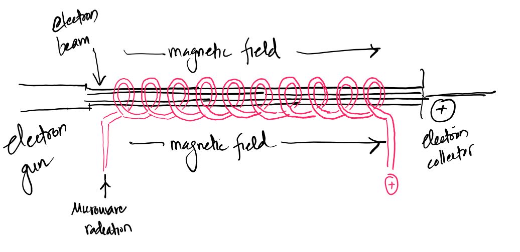
A Backward Wave Oscillator is a microwave vacuum tube belonging to the traveling-wave tube family and is designed primarily as a microwave source. It can generate frequencies extending into the terahertz range and provides a particularly useful electronic tuning capability. The basic structure consists of an electron gun, an electron beam, a periodic slow-wave circuit, a magnetic focusing system, and a collector. The electron gun generates and accelerates the electron beam, while the magnetic field keeps the beam properly focused as it travels through the interaction region. The slow-wave structure supports electromagnetic waves having a longitudinal electric-field component, allowing the RF field to interact effectively with the electron beam. In the BWO, the useful interacting wave propagates in the backward direction, meaning that its energy or group propagation is directed toward the electron-gun side while the electrons move toward the collector. The electron beam transfers energy to this backward wave, causing its amplitude to grow and producing sustained microwave oscillation. The output power is then coupled from the slow-wave structure near the electron-gun end.
Working Principle of the Backward Wave Oscillator
The operation of a BWO is based on continuous interaction between an electron beam and a periodic slow-wave structure. The slow-wave circuit is constructed so that the phase velocity of an appropriate space harmonic can be made comparable with the velocity of the electron beam. When the synchronism condition is satisfied, the electrons experience the longitudinal RF electric field of the slow-wave structure. Depending on their position relative to the RF field, some electrons are accelerated while others are decelerated. The electrons that encounter a decelerating RF field lose kinetic energy, and this energy is transferred to the electromagnetic wave. As the interaction continues along the periodic structure, the backward wave receives energy from the electron beam and grows in amplitude. Since the wave propagates toward the electron-gun side, the output is coupled out near the input side of the electron beam rather than at the collector end as in an ordinary forward-wave TWT amplifier. The process therefore provides the self-sustained energy transfer required for microwave oscillation.
Backward-Wave Propagation and Electron-Beam Interaction
The distinguishing feature of the BWO is the direction of propagation of the useful electromagnetic wave. In an ordinary traveling-wave amplifier, the RF wave generally travels along the slow-wave structure in the same general direction as the electron beam. In a BWO, the interacting wave is a backward wave whose group velocity is opposite to the direction of electron motion. The electron beam therefore moves toward the collector while the useful wave carries electromagnetic energy toward the electron-gun side. This opposite-direction propagation is responsible for the name Backward Wave Oscillator. The slow-wave circuit must provide a longitudinal RF electric field so that the electrons can exchange energy with the wave. It must also have a periodic structure capable of supporting suitable pass bands, stop bands, and space harmonics. Because of the periodic geometry, the electromagnetic fields repeat from cell to cell with a constant phase shift, allowing the appropriate space harmonic to interact strongly with the electron beam.
Slow-Wave Structure Used in BWO
A typical BWO uses a periodic folded transmission line or folded waveguide as its slow-wave structure. This folded structure performs a function similar to the helix in a conventional TWT by increasing the effective path followed by the electromagnetic wave and thereby reducing its axial phase velocity. The periodic nature of the structure is important because it produces space harmonics of the electromagnetic field. Strong beam-wave interaction occurs when the phase velocity of a suitable space harmonic is close to the electron velocity. The geometry of the slow-wave structure therefore determines the range of frequencies and interaction conditions that can be supported. Since the spacing and periodic dimensions of the structure are fixed, the supported waveguide frequency range is also constrained. However, the oscillation frequency can be changed electronically by changing the electron-beam transit time, which provides the BWO with its important frequency-tuning capability.
Electronic Tuning of a BWO
One of the major advantages of the BWO is its wide electronic frequency tuning capability. The frequency of oscillation depends strongly on the interaction between the periodic slow-wave structure and the velocity of the electron beam. The electron velocity is controlled by the accelerating potential applied to the beam. For an electron accelerated through a voltage \(V_0\), the approximate electron velocity is given by:
\[ u_0=\sqrt{\frac{2eV_0}{m}} \]
where \(e\) is the magnitude of the electron charge and \(m\) is the electron mass. Changing the accelerating voltage changes the electron velocity and therefore changes the synchronism condition between the electron beam and the backward space harmonic. Consequently, the frequency of the generated microwave signal can be electronically tuned by varying the beam voltage. This is a major advantage of the BWO compared with microwave sources whose operating frequency is determined primarily by fixed resonant dimensions.
Types of Backward Wave Oscillator
There are two principal types of backward wave oscillators: the O-type BWO and the M-type BWO. The O-type BWO uses a longitudinal electron beam that is focused by a magnetic field and interacts with a periodic slow-wave circuit. The electron beam travels through the interaction structure and is finally collected by the collector. The M-type BWO operates on a different beam configuration and uses crossed static electric and magnetic fields. The electron motion is controlled by these fields while the electron sheet beam interacts with the slow-wave circuit. The M-type configuration can provide very high power and uses electric and magnetic field components of the RF interaction differently from the O-type configuration. Both types use beam-wave interaction with a backward electromagnetic wave, but their electron-beam arrangements and focusing mechanisms are different.
O-Type Backward Wave Oscillator
In the O-type Backward Wave Oscillator, the electron beam is directed longitudinally through the slow-wave interaction structure and is focused by a magnetic field. The slow-wave circuit is positioned around or along the electron-beam path so that its longitudinal RF electric-field component can interact with the electrons. When the electron velocity and the phase velocity of the appropriate backward space harmonic satisfy the required synchronism condition, electrons moving through the decelerating portion of the RF field transfer kinetic energy to the wave. The backward wave grows as it propagates toward the electron-gun side, while the electron beam continues toward the collector. The collector absorbs the remaining electron beam after the interaction. The O-type arrangement is closely related to the conventional TWT beam-wave interaction principle, but the traveling-wave direction and operating condition are selected so that the device produces self-sustained oscillation rather than functioning only as a forward-wave amplifier.
M-Type Backward Wave Oscillator
The M-type Backward Wave Oscillator uses crossed static electric and magnetic fields and is therefore related in principle to the type of electron motion found in magnetron-like devices. A sheet electron beam drifts through the slow-wave circuit under the influence of the crossed static fields, with the electron motion controlled by the combined electric and magnetic fields. Strong interaction occurs when the phase velocity of an appropriate space harmonic becomes equal or sufficiently close to the electron velocity. Both longitudinal and transverse components of the RF electric field can participate in the interaction. Electrons encountering a decelerating component of the RF field lose energy, and this energy is transferred to the electromagnetic wave in the slow-wave circuit. The M-type configuration is particularly important when high output power is required, while the O-type configuration provides a more direct traveling-wave electron-beam arrangement.
Why BWO Is Considered an Oscillator
The essential difference between a TWT amplifier and a BWO is the way energy is generated and sustained. A conventional TWT amplifier starts with an externally supplied RF signal and uses the electron beam to increase its amplitude. A BWO, in contrast, is designed so that the backward traveling wave can interact with the electron beam and continuously receive energy from it. The wave is reinforced by the electron beam as it travels through the interaction structure, and the appropriate boundary and synchronism conditions allow a self-sustained oscillation to develop. The output is coupled from the backward-wave side of the structure, near the electron gun. Therefore, the BWO demonstrates how the traveling-wave tube family can be used not only for amplification but also for microwave generation when the slow-wave structure, beam velocity, wave direction, and interaction conditions are arranged for oscillator operation.
Feedback Technique and Oscillation Mechanism in Traveling Wave Tube
The Traveling Wave Tube (TWT) is normally designed as a microwave amplifier, but oscillation can be obtained when the amplified RF output is fed back to the input with the proper magnitude and phase. In this arrangement, the electron beam and helix continue to provide the energy required to amplify the RF wave, while the feedback path returns a controlled portion of the output signal to the input. If the returned signal is sufficiently strong and arrives with the correct phase, it reinforces the signal already present at the input and the RF amplitude increases on successive passes through the interaction system. When the gain and feedback satisfy the required oscillation condition, the device can sustain microwave oscillation without requiring a continuously applied external RF drive. The resulting configuration is commonly referred to as a Traveling Wave Tube Oscillator (TWTO).
RF Signal Generation Through Feedback
In a TWT oscillator, the RF signal does not have to originate from a conventional external microwave source. A very small initial disturbance, such as electronic noise or a small RF fluctuation within the system, can provide the initial signal. This signal interacts with the electron beam through the helix and is amplified as it travels along the slow-wave structure. A controlled portion of the amplified output is then returned toward the input through a feedback path. The returned signal acts as a new input signal and undergoes further amplification. This process can repeat continuously, allowing the RF signal to grow from a very small initial disturbance into a substantial microwave oscillation. The electron beam supplies the energy for this growth, while the feedback path determines whether the amplified signal is returned in a manner that reinforces the oscillation.
Output-to-Input Feedback Path
The essential modification required for oscillator operation is the introduction of a suitable output-to-input feedback path. In ordinary amplifier operation, the output is isolated from the input so that the amplified signal does not return strongly enough to produce unwanted oscillation. For oscillator operation, a controlled portion of the output RF energy is deliberately coupled back to the input. This can be implemented using a suitable microwave coupling or feedback network arranged between the output and input sections. The feedback network must provide the required amount of coupling while maintaining the appropriate phase relationship. Too little feedback may not provide enough signal reinforcement to sustain oscillation, whereas excessive or poorly controlled feedback can produce instability, unwanted modes, or undesirable changes in output behavior. The feedback path therefore becomes an important part of the oscillator design rather than an unwanted parasitic effect.
Phase Relationship and Constructive Feedback
Magnitude alone is not sufficient to produce sustained oscillation. The RF signal returning through the feedback path must have the correct phase relative to the signal at the input. For constructive feedback, the returned signal must reinforce the existing RF oscillation rather than cancel it. The total phase shift around the complete loop must therefore satisfy the required oscillation condition. In general, the loop phase condition can be expressed as:
\[ \angle A\beta=2\pi n \]
where \(A\) is the forward gain of the TWT, \(\beta\) is the feedback factor, and \(n\) is an integer. This condition means that after passing through the TWT and the feedback network, the signal returns to the input with a phase that reinforces the original signal. If the phase condition is not satisfied, the returned signal may partially or completely oppose the original signal, preventing sustained oscillation at that frequency.
Loop Gain and Oscillation Condition
The magnitude of the loop gain determines whether the initial RF disturbance grows or decays. If \(A\) represents the forward voltage or field gain of the TWT and \(\beta\) represents the feedback factor, the magnitude of the loop gain is:
\[ |A\beta| \]
For oscillation to begin, the feedback signal must be sufficiently large to compensate for the losses encountered around the loop. The starting condition can therefore be expressed as:
\[ \boxed{|A\beta|\geq1} \]
When \(|A\beta|<1\), the signal becomes smaller after each loop and sustained oscillation cannot develop. When \(|A\beta|=1\), the feedback exactly compensates for the losses and a steady oscillation can be maintained. During the initial build-up of oscillation, the loop gain can effectively be greater than unity, allowing the amplitude to increase from a small disturbance. As the RF signal becomes large, nonlinear effects in the TWT reduce the effective gain until the loop reaches a stable operating condition in which the available gain and feedback losses balance.
Barkhausen-Type Condition for TWT Oscillation
The two fundamental requirements for oscillation can therefore be expressed as a magnitude condition and a phase condition. The magnitude condition requires the loop gain to be at least unity for oscillation to start, while the phase condition requires the total phase shift around the loop to be an integral multiple of \(2\pi\). These conditions are commonly expressed together as:
\[ \boxed{|A\beta|\geq1} \]
and:
\[ \boxed{\angle A\beta=2\pi n} \]
For a practical steady-state oscillator, the effective loop gain settles close to unity at the operating amplitude. The exact behavior depends on the TWT gain characteristics, feedback network, beam voltage, slow-wave structure, frequency, loading, and nonlinear saturation effects. Therefore, the Barkhausen-type conditions provide the fundamental conceptual description of oscillation, while the actual oscillator design must also account for the frequency-dependent gain and losses of the complete microwave structure.
Growth of Oscillation From an Initial Disturbance
Once the feedback path and phase condition are appropriate, the oscillator can begin from a very small RF disturbance. Suppose a small signal appears at the TWT input. The electron beam transfers part of its kinetic energy to the RF wave through continuous interaction with the helix, producing an amplified output. A controlled fraction of this output is fed back to the input. If the returned signal is in phase with the existing RF signal and the loop gain is greater than unity, the next RF signal is larger than the previous one. Repetition of this process causes the oscillation amplitude to grow progressively. The growth does not continue indefinitely because the TWT is a nonlinear high-power device. As the RF field becomes stronger, the electron beam interaction becomes nonlinear and the available gain decreases. Eventually, the loop reaches a condition in which the effective gain is approximately equal to the total losses, producing a stable oscillation amplitude.
Role of the Electron Beam and Helix
The feedback network alone does not generate microwave power. The energy required for the growing RF oscillation comes from the DC electron beam. The electron gun produces and accelerates the beam, and the magnetic focusing system maintains the beam along the interaction region. The helix acts as the slow-wave structure, allowing the RF wave to travel with a phase velocity suitable for interaction with the electron beam. As the RF field interacts continuously with the electrons, the beam undergoes velocity and density modulation, producing electron bunching. Electrons that encounter the appropriate decelerating phase of the RF field transfer kinetic energy to the traveling electromagnetic wave. The RF wave therefore gains energy from the beam as it propagates, while the feedback network returns part of this amplified energy to the input to maintain the oscillation. In this way, the DC beam provides the energy source, the helix provides the continuous beam-wave interaction mechanism, and the feedback network provides the regeneration required for self-sustained oscillation.
Continuous Beam-Wave Interaction and Sustained Oscillation
Unlike a resonant-cavity oscillator in which energy is concentrated in a localized cavity resonance, a TWT-based oscillator relies on interaction between the electron beam and a traveling electromagnetic wave along the slow-wave structure. The RF wave is continuously reinforced by energy transferred from the electron beam, while the feedback path returns a portion of the resulting RF signal to the input. When the returned signal has the correct phase and sufficient magnitude, the process repeats and the oscillation is maintained. The frequency at which these conditions are simultaneously satisfied becomes a preferred oscillation frequency. The slow-wave structure, electron-beam velocity, feedback path, and phase delay therefore work together to determine the operating condition of the oscillator.
Saturation and Stabilization of Oscillator Output
During start-up, the RF amplitude increases because the loop gain is greater than unity. However, a practical TWT does not provide unlimited gain. As the RF input and beam-wave interaction become stronger, the device approaches its saturation region. The effective gain decreases as the electron beam becomes increasingly modulated and the available energy transfer becomes limited. Consequently, the loop gain approaches unity and the RF output settles to a stable level. This process is important because a useful oscillator must not continue increasing in amplitude without limit. The final output level is determined by the available electron-beam power, TWT gain, feedback factor, slow-wave interaction, output loading, and nonlinear saturation characteristics.
Why Feedback Must Be Controlled in an Ordinary TWT
In a normal TWT amplifier, feedback is generally undesirable because an unintended portion of the output signal returning to the input can produce unwanted oscillation or instability. For this reason, TWTs commonly incorporate measures such as internal attenuation and careful microwave isolation to suppress reflections and prevent the amplified output from coupling back into the input. In an oscillator configuration, the situation is deliberately reversed: a controlled feedback path is introduced so that a selected portion of the output is returned to the input with the required magnitude and phase. The feedback must remain controlled because uncontrolled reflections can cause frequency instability, unwanted oscillation modes, distortion, or unreliable operation. Thus, the distinction between a TWT amplifier and a TWT oscillator is closely connected to whether the output is isolated from the input or deliberately coupled back to it under controlled oscillation conditions.
Overall Oscillation Process in a TWT
The complete mechanism can be understood as a continuous sequence beginning with a small RF disturbance. The disturbance enters the interaction region, where the helix slows the RF wave sufficiently for effective interaction with the electron beam. The RF field produces velocity modulation and density modulation of the beam, leading to electron bunching. The bunched electrons transfer kinetic energy to the traveling RF wave, causing the RF signal to become stronger along the helix. A controlled portion of this amplified output is then fed back to the input. If the feedback has the correct phase and the loop gain is sufficient to overcome the losses, the returned signal reinforces the existing RF field. The process repeats, causing the oscillation amplitude to grow until nonlinear saturation reduces the effective gain and a stable microwave output is established.
Initial RF disturbance → TWT beam-wave interaction → RF amplification → Output coupling → Controlled feedback → Phase-aligned input reinforcement → Repeated amplification → Saturation → Sustained microwave oscillation
Backward Wave Oscillator (BWO) in detail
The Backward Wave Oscillator (BWO), also known as a carcinotron, is a special type of microwave vacuum tube belonging to the traveling-wave tube family. It is mainly used as a microwave source and can generate oscillations at very high frequencies, extending into the terahertz range. Like a Traveling Wave Tube (TWT), the BWO uses an electron beam and a slow-wave structure for continuous interaction between the electrons and an electromagnetic field. The important difference is that the useful electromagnetic wave in a BWO travels in the direction opposite to the motion of the electron beam. The electron beam transfers part of its kinetic energy to this backward wave, allowing microwave oscillations to be generated. Another important feature of the BWO is its wide electronic frequency tuning capability, because the oscillation frequency can be controlled by changing the electron-beam velocity through the applied beam or collector voltage.
What Is a Backward Wave Oscillator?
A Backward Wave Oscillator is a microwave vacuum tube designed to generate high-frequency electromagnetic oscillations using continuous interaction between an electron beam and a periodic slow-wave structure. The device belongs to the broader family of traveling-wave tubes because its operation depends on the interaction of an electron beam with a traveling electromagnetic wave rather than relying only on a conventional resonant cavity. The name backward wave oscillator comes from the direction of the useful RF wave: the electron beam travels from the electron gun toward the collector, while the interacting electromagnetic wave travels backward toward the electron-gun side. During this interaction, electrons that encounter an appropriate decelerating phase of the RF electric field lose kinetic energy, and this energy is transferred to the electromagnetic wave. The resulting wave is reinforced along the interaction structure and produces microwave oscillation.
BWO as a Member of the Traveling Wave Tube Family
The BWO and TWT are closely related because both use an electron beam, a slow-wave structure, magnetic focusing, and continuous beam-wave interaction. In a conventional TWT amplifier, an externally supplied RF signal is injected into the slow-wave structure and amplified as it interacts progressively with the electron beam. The electron beam supplies energy to the traveling RF signal, producing a larger output signal at the end of the interaction structure. A BWO uses the same fundamental principle of transferring energy from the electron beam to an electromagnetic wave, but the device is arranged to support a backward wave and self-sustained oscillation. Thus, the BWO can be viewed as a specialized traveling-wave device in which the slow-wave structure and electron-beam conditions are selected to produce microwave generation rather than ordinary forward-wave amplification.
Why Is BWO Also Called a Carcinotron?
The term carcinotron is another name historically associated with the Backward Wave Oscillator. The device was developed as a microwave source based on backward-wave interaction in a periodic slow-wave circuit. The name is therefore commonly encountered when studying the historical development and classification of microwave vacuum tubes. Regardless of the terminology, the fundamental operating principle remains the same: a periodic slow-wave structure interacts with an electron beam, and an appropriate backward space harmonic extracts energy from the beam to generate microwave oscillations.
Construction of Backward Wave Oscillator
A typical BWO consists of an electron gun, periodic slow-wave structure, magnetic focusing system, collector, and RF output coupling arrangement. The electron gun produces and accelerates the electron beam to the required velocity. The beam then passes through the slow-wave interaction region, where it interacts continuously with the RF electromagnetic field. The slow-wave structure is usually periodic and may be formed using a folded transmission line, folded waveguide, or a related periodic circuit. This structure performs a function similar to the helix used in a TWT by reducing the effective axial phase velocity of the electromagnetic wave and providing suitable space harmonics for beam-wave interaction. A magnetic focusing system surrounds the interaction region to prevent the electron beam from spreading and to maintain the required beam path. After passing through the interaction region, the remaining electron beam is collected by the collector. Since the useful RF wave travels backward toward the electron-gun side, the output coupling arrangement is located near that side of the slow-wave structure.
Electron Gun and Electron Beam Formation
The electron gun is responsible for generating and accelerating the electron beam used in the BWO. Electrons emitted from the cathode are accelerated by an applied electric potential, giving them a high velocity before they enter the slow-wave interaction region. The approximate velocity of an electron beam accelerated through a voltage \(V_0\) is:
\[ u_0=\sqrt{\frac{2eV_0}{m}} \]
where \(e\) is the magnitude of the electron charge and \(m\) is the electron mass. The beam velocity is extremely important because the frequency and strength of beam-wave interaction depend on the relationship between electron velocity and the phase velocity of the appropriate space harmonic. The electron beam must therefore be properly formed and focused so that it remains concentrated through the slow-wave structure and interacts effectively with the RF field.
Slow-Wave Structure of BWO
The slow-wave structure is the main interaction circuit of the BWO. A typical structure may consist of a folded transmission line or folded waveguide that repeatedly winds across the path of the electron beam. The purpose of folding the electromagnetic path is to reduce the effective axial phase velocity of the wave so that it can interact efficiently with the much slower electron beam. The periodic arrangement also produces space harmonics of the electromagnetic field. For effective interaction, the phase velocity of a suitable space harmonic must be close to the electron velocity. The slow-wave structure must also support an RF electric field with a longitudinal component because this component interacts directly with the electron beam and allows energy to be transferred between the electrons and the electromagnetic wave.
Magnetic Focusing System and Collector
The electron beam in a BWO must remain sufficiently narrow and aligned throughout the interaction region. A magnetic focusing system is therefore placed around the body of the tube to control the transverse motion of the electrons and prevent excessive beam spreading. Proper focusing improves the interaction between the electron beam and the slow-wave field and helps maintain stable operation. After the electron beam has completed its interaction with the slow-wave structure, it reaches the collector, which absorbs the remaining electrons. The collector is therefore the final destination of the electron beam, whereas the useful backward electromagnetic wave travels in the opposite direction toward the electron-gun side.
Backward-Wave Propagation
The most distinctive feature of the BWO is the backward propagation of the useful electromagnetic wave. The electron beam moves from the electron gun toward the collector, while the interacting RF wave propagates toward the electron-gun side. Therefore, the direction of the useful wave is opposite to the direction of electron-beam motion. More specifically, the group velocity associated with the generated electromagnetic wave is directed opposite to the electron velocity. The periodic slow-wave structure makes this possible by supporting appropriate space harmonics whose phase and group propagation characteristics permit energy transfer from the electron beam to the backward wave. This opposite-direction interaction is the fundamental reason the device is called a Backward Wave Oscillator.
Velocity Modulation and Electron Bunching
The BWO uses the principle of velocity modulation to establish effective beam-wave interaction. As the electron beam passes through the RF electric field of the slow-wave structure, electrons at different positions encounter different phases of the field. Some electrons are accelerated while others are decelerated, producing variations in their velocities. Faster electrons gradually catch up with slower electrons, causing the electrons to become concentrated into groups called electron bunches. This process produces density modulation of the electron beam. When these bunched electrons encounter the appropriate decelerating phase of the RF field, they lose kinetic energy, and the lost energy is transferred to the electromagnetic wave. The continuous interaction between the electron bunches and the backward RF wave allows the wave to gain energy from the electron beam and supports the generation of microwave oscillations.
Energy Transfer From Electron Beam to the Backward Wave
The electron beam is the source of energy that sustains the microwave oscillation. The electrons are initially given kinetic energy by the accelerating voltage of the electron gun. As the beam travels through the slow-wave structure, the RF electric field modifies the electron velocities and produces bunching. Electrons arriving in the decelerating phase of the RF field give up part of their kinetic energy to the electromagnetic wave. The backward wave therefore becomes stronger as energy is continuously transferred from the beam. This process is fundamentally different from simply reflecting a microwave signal: the electron beam actively supplies energy to the RF field. The slow-wave structure provides the required field distribution and synchronism, while the electron beam provides the energy required to maintain the oscillation.
Space Harmonics and Periodic Slow-Wave Structure
The periodic geometry of the BWO slow-wave structure is essential because it produces a set of space harmonics of the electromagnetic field. The electromagnetic fields in successive sections of the periodic structure have similar characteristics but differ in phase by a constant amount. These space harmonics have different phase velocities, allowing one of them to satisfy the required synchronism condition with the electron beam. The interaction is normally strongest with the fundamental or a low-order space harmonic because higher-order harmonics generally have smaller field amplitudes. Therefore, the geometry and periodicity of the slow-wave structure are carefully selected to produce an appropriate space harmonic with a phase velocity suitable for efficient interaction with the electron beam.
Output Coupling in BWO
Because the useful electromagnetic wave travels backward, the RF output is coupled from the slow-wave structure near the electron-gun side of the tube. This is an important structural difference from a conventional forward-wave TWT, where the amplified RF output is normally obtained near the end of the structure in the direction of wave propagation. In the BWO, the backward wave carries the generated electromagnetic energy toward the gun side, where an output coupling arrangement extracts the microwave signal from the interaction circuit. The electron beam, meanwhile, continues forward and is finally collected by the collector.
Electronic Frequency Tuning of BWO
One of the major advantages of the BWO is its wide electronic frequency tuning capability. The oscillation frequency is determined by the interaction between the electron-beam velocity and the electromagnetic wave supported by the periodic slow-wave structure. Since the electron velocity depends on the applied beam voltage, changing the voltage changes the synchronism condition and therefore changes the frequency of oscillation. For an electron accelerated through \(V_0\), the beam velocity is approximately:
\[ u_0=\sqrt{\frac{2eV_0}{m}} \]
As the beam voltage is varied, the electron transit time through the interaction structure also changes. The resulting change in beam velocity modifies the frequency at which the required beam-wave synchronism occurs. Consequently, the BWO can be electronically tuned over a relatively wide frequency range without mechanically changing the dimensions of the slow-wave structure. In practical descriptions of BWO operation, the collector or beam potential is therefore associated with electronic control of the oscillation frequency. This voltage-controlled tuning is one of the most useful characteristics of the BWO as a microwave source.
Relationship Between BWO and TWT
The BWO can be understood as a specialized member of the traveling-wave tube family because both devices use continuous interaction between an electron beam and a slow-wave structure. The fundamental beam-wave interaction, velocity modulation, electron bunching, and transfer of electron kinetic energy to the electromagnetic field are common to both devices. The major difference lies in the operating mode and wave direction. A conventional TWT is normally used as an amplifier and requires an external RF signal that is progressively amplified along the slow-wave structure. A BWO is designed to generate oscillations by using a backward wave that travels opposite to the electron beam and receives energy from the beam. The BWO therefore uses the traveling-wave principle in an oscillator configuration, making it a useful tunable microwave source rather than simply an RF amplifier.
BWO Oscillation Mechanism, Performance, Advantages, Disadvantages and Applications
The Backward Wave Oscillator (BWO) generates microwave power through continuous interaction between an electron beam and a backward electromagnetic wave supported by a periodic slow-wave structure. The electron beam travels from the electron gun toward the collector, while the useful RF wave propagates in the opposite direction toward the electron-gun side. When the velocity of the electron beam is properly synchronized with the phase velocity of a suitable backward space harmonic, the electrons interact strongly with the RF electric field and transfer part of their kinetic energy to the electromagnetic wave. This energy transfer continuously increases the RF field, allowing oscillation to be sustained. The oscillation frequency is determined by the beam-wave synchronism condition and can therefore be controlled electronically by changing the beam voltage. These characteristics make the BWO a useful high-frequency microwave source with wide electronic tunability and operation extending into very high-frequency and terahertz regions.
Backward-Wave Oscillation Mechanism
The oscillation mechanism begins when the electron gun produces and accelerates an electron beam through the interaction region. The periodic slow-wave structure supports electromagnetic waves and their space harmonics, including a backward wave suitable for interaction with the electron beam. As the electrons pass through the RF field, their velocities are modified according to the phase of the electric field encountered by each electron. This velocity modulation produces density modulation and electron bunching. When the electron bunches arrive at a phase of the backward RF field where the electric field opposes their motion, the electrons are decelerated and lose kinetic energy. The lost kinetic energy is transferred to the electromagnetic field, increasing the amplitude of the backward wave. The strengthened wave continues to interact with the electron beam, producing further energy transfer and maintaining the oscillation. The wave eventually reaches the output coupling region near the electron-gun side, where the generated microwave power is extracted.
Synchronism Between Electron Beam and Backward Space Harmonic
Efficient interaction requires synchronism between the electron beam and an appropriate space harmonic of the electromagnetic wave. The electron beam velocity is controlled by the accelerating voltage, while the phase velocity of the interacting space harmonic is determined mainly by the periodic slow-wave structure. Strong interaction occurs when the phase velocity of the selected space harmonic is sufficiently close to the electron velocity. Under this condition, the electrons remain in effective interaction with the RF field over a significant portion of the interaction region. The periodic structure is especially important because it creates space harmonics having different phase velocities, making it possible for one of these harmonics to satisfy the required beam-wave interaction condition. This synchronism is one of the fundamental requirements for obtaining efficient energy transfer and stable BWO operation.
The approximate velocity of an electron beam accelerated through a voltage \(V_0\) is:
\[ u_0=\sqrt{\frac{2eV_0}{m}} \]
where \(e\) is the magnitude of the electron charge and \(m\) is the electron mass. Increasing or decreasing the beam voltage changes \(u_0\), which changes the synchronism condition with the backward space harmonic. Consequently, the oscillation frequency can be controlled electronically through the beam voltage.
Energy Transfer From Electron Beam to RF Wave
The electron beam provides the energy required for microwave generation. The electrons first acquire kinetic energy from the accelerating electric field produced by the beam voltage. During their passage through the slow-wave structure, the RF electric field periodically accelerates and decelerates the electrons. For oscillation to be sustained, a significant portion of the electrons must interact with the decelerating phase of the RF field. These electrons lose kinetic energy, and the energy appears as an increase in the electromagnetic field of the backward wave. The slow-wave structure therefore acts as the interaction medium, while the electron beam acts as the energy source. The continuous nature of the interaction allows energy to be transferred over the length of the structure rather than only at a single localized resonant cavity.
Role of the Decelerating RF Field
The decelerating RF field plays a central role in BWO operation because energy can be transferred from the electron beam to the electromagnetic wave only when the electrons experience the appropriate phase of the RF field. Electrons that encounter an accelerating field gain energy from the RF field, whereas electrons encountering a decelerating field lose kinetic energy. For useful oscillator operation, the beam-wave interaction is arranged so that the net energy transfer is from the electron beam to the RF wave. The resulting RF field becomes stronger as it propagates backward through the slow-wave structure. Proper electron bunching increases the number of electrons interacting in the useful phase and therefore improves the transfer of beam energy into microwave power.
Continuous Growth of the Backward Wave
As the backward wave interacts with the electron beam, the RF field receives energy continuously along the slow-wave structure. This produces progressive growth of the electromagnetic wave rather than amplification at only one point. The periodic structure ensures that the field remains capable of interacting with the electron beam over successive sections. When the synchronism condition is satisfied, electron bunches continue to encounter the appropriate decelerating field and transfer additional energy to the wave. The backward wave therefore becomes progressively stronger as it moves toward the output coupling region. This continuous beam-wave interaction is the key feature that connects the BWO with the traveling-wave tube family while its backward-wave condition distinguishes it from a conventional forward-wave TWT amplifier.
Oscillation and Frequency Selection
The oscillation frequency of a BWO is established by the combined characteristics of the periodic slow-wave structure and the electron beam. The slow-wave circuit supports particular electromagnetic modes and space harmonics, while the electron beam provides a velocity that can be adjusted through the applied voltage. Oscillation becomes strong at frequencies for which the appropriate backward space harmonic and the electron beam satisfy the required interaction condition. Therefore, the BWO does not select its operating frequency solely through a fixed resonant cavity. Instead, frequency selection results from the interaction between the dispersion characteristics of the periodic slow-wave structure and the electron-beam velocity. This provides the BWO with an important electronic tuning capability.
Relationship Between Beam Transit Time and Oscillation Frequency
The electron transit time through the interaction structure is closely related to the operating frequency because the electrons must remain in the correct phase relationship with the RF field during interaction. The transit time can be represented generally as:
\[ t_t=\frac{L}{u_0} \]
where \(L\) is the effective interaction length and \(u_0\) is the electron-beam velocity. Since:
\[ u_0=\sqrt{\frac{2eV_0}{m}} \]
changing the beam voltage changes the electron velocity and therefore changes the transit time. A change in transit time modifies the phase relationship between the electron beam and the periodic RF field. The frequency at which the required interaction condition is obtained therefore changes with the beam voltage. This beam-transit-time dependence is an important part of the electronic tuning principle of the BWO.
Electronic Tuning Characteristics
Electronic tuning is one of the most important advantages of a BWO. By varying the accelerating or collector potential, the velocity of the electron beam can be changed, which shifts the frequency at which the required synchronism condition is satisfied. The frequency can therefore be varied over a wide range without mechanically changing the physical dimensions of the slow-wave structure. The fixed periodic dimensions of the slow-wave circuit still determine the general operating region and available modes, but the electron-beam velocity provides an additional means of selecting the operating frequency within the supported range. This makes the BWO particularly useful as a voltage-tunable microwave source for systems requiring frequency sweeping or rapid electronic frequency adjustment.
Frequency Range and High-Frequency Operation
BWOs are capable of operation at extremely high frequencies because their periodic slow-wave structures can be designed for very short electromagnetic wavelengths and the electron-beam interaction can be maintained at high frequencies. Depending on the design, BWO operation can extend from the microwave region into the terahertz range. A commonly cited broad operating range is approximately \(1\) to \(1000\) GHz, although the practical range depends strongly on the specific BWO design, slow-wave structure, electron-beam parameters, and operating mode. The ability to reach very high frequencies is one of the reasons BWOs have been used as specialized microwave and submillimeter-wave sources.
Output Power Characteristics
The output power of a BWO depends on the electron-beam power, slow-wave interaction, operating frequency, device type, and efficiency of energy conversion. O-type BWOs generally operate at relatively modest output power, while M-type BWOs can provide substantially higher power and are considered the more powerful of the two principal BWO configurations. Representative O-type devices have been reported with output powers ranging from approximately \(1\) mW at \(1\) THz to about \(50\) mW at \(200\) GHz. These values are device-dependent and should therefore be treated as representative rather than universal performance limits. The primary importance of the BWO is often its combination of very high operating frequency and wide electronic tuning rather than exceptionally high output power.
Signal Stability and Signal-to-Noise Characteristics
The BWO is valued as a microwave source because it can provide a well-defined and electronically tunable output signal. The interaction between the electron beam and the selected slow-wave mode determines the operating frequency, while the beam voltage provides electronic control over that interaction. Properly designed devices can provide high-frequency stability and a strong output signal over their intended operating range. BWO performance can also be described in terms of signal-to-noise ratio, and very high signal-to-noise performance has been reported for suitable BWO systems, with values as high as approximately \(120\) dB per MHz under specified operating conditions. Actual signal quality depends on beam stability, power-supply stability, slow-wave structure, operating mode, and the particular device design.
Advantages of Backward Wave Oscillator
The BWO offers several important advantages as a microwave source. Its most distinctive advantage is its wide electronic frequency tunability, since the oscillation frequency can be controlled by varying the electron-beam voltage. It can operate at extremely high frequencies and can extend into the terahertz region, making it useful for applications where conventional microwave sources become difficult to implement. The BWO can also generate a sharply defined microwave signal and provide useful frequency stability when operated under suitable conditions. Since the operating frequency can be adjusted electronically, the BWO is particularly useful in microwave measurement systems, frequency-swept sources, and high-frequency experimental systems.
Disadvantages and Practical Limitations of BWO
Despite its advantages, the BWO has several practical limitations. Its efficiency is generally lower than that of many TWT and klystron configurations, which limits the amount of useful RF power that can be obtained for a given electron-beam power. The periodic slow-wave structure also places restrictions on the available operating bands because its fixed geometry determines the supported electromagnetic modes and space harmonics. The device requires an electron gun, focusing system, high-voltage supply, precision slow-wave structure, and collector, making its construction and operation more complex than those of many solid-state microwave sources. In addition, maintaining the required beam-wave synchronism and stable operating voltage is important for reliable performance.
Applications of Backward Wave Oscillator
The BWO is mainly used in applications where a tunable and stable microwave source is required. Its wide electronic frequency tuning makes it useful as a variable-frequency signal source in microwave laboratories and measurement systems. It can be used for frequency-swept measurements, microwave test equipment, high-frequency signal generation, and specialized communication or research systems. Because some BWO designs can operate into the terahertz region, they are also useful in experimental systems involving submillimeter-wave and terahertz generation. The ability to electronically change the operating frequency by controlling the beam voltage is particularly valuable in systems where rapid or continuous frequency adjustment is required.
Overall Operation of Backward Wave Oscillator
The complete operation of a Backward Wave Oscillator can be understood as a continuous sequence beginning with electron generation and acceleration. The electron gun produces an electron beam and accelerates it to the required velocity. The magnetic focusing system maintains the beam through the periodic slow-wave structure. The periodic circuit supports a suitable backward space harmonic having an appropriate longitudinal RF electric-field component. When the electron velocity and the phase velocity of this space harmonic satisfy the required synchronism condition, the RF field produces velocity modulation and electron bunching. Electrons arriving in the decelerating phase of the RF field lose kinetic energy, and this energy is transferred to the backward electromagnetic wave. The wave grows continuously as it interacts with the beam and travels toward the electron-gun side. The generated RF power is then coupled out near the gun, while the remaining electron beam continues to the collector. Changing the beam or collector voltage changes the electron velocity and therefore the synchronism condition, allowing the BWO frequency to be electronically tuned.
Electron gun → Electron-beam acceleration → Magnetic focusing → Slow-wave interaction → Velocity modulation → Electron bunching → Energy transfer to backward wave → Progressive RF growth → Output coupling → Tunable microwave output