Cavity Magnetron
Cavity Magnetron: Introduction, Construction and Cross-Field Effect
A cavity magnetron is a high-power microwave device that operates as a cross-field tube, in which the electric and magnetic fields are perpendicular to each other. Unlike conventional vacuum tubes in which the electric field primarily controls the motion of electrons, a magnetron uses the combined effect of electric and magnetic fields to control the electron trajectory and enable efficient interaction between the electron beam and the radio-frequency field. The magnetron is called a cavity magnetron because its anode is formed with a number of resonant cavities that support microwave oscillations. A strong dc magnetic field is produced by a permanent magnet or electromagnet, while a dc voltage establishes the electric field between the cathode and anode. The crossed electric and magnetic fields cause the electrons emitted from the cathode to follow curved paths instead of travelling directly toward the anode. This controlled electron motion allows the electrons to interact with the high-frequency fields associated with the resonant cavities for a relatively long time, making the cavity magnetron highly effective for generating high-power microwave signals. The same principle of maintaining a longer interaction between the electron beam and the RF field is important in microwave devices because extended interaction can improve the transfer of energy from the electron beam to the electromagnetic field.
Briefly describe the construction and operational features of a cavity magnetron
Construction of Cavity Magnetron
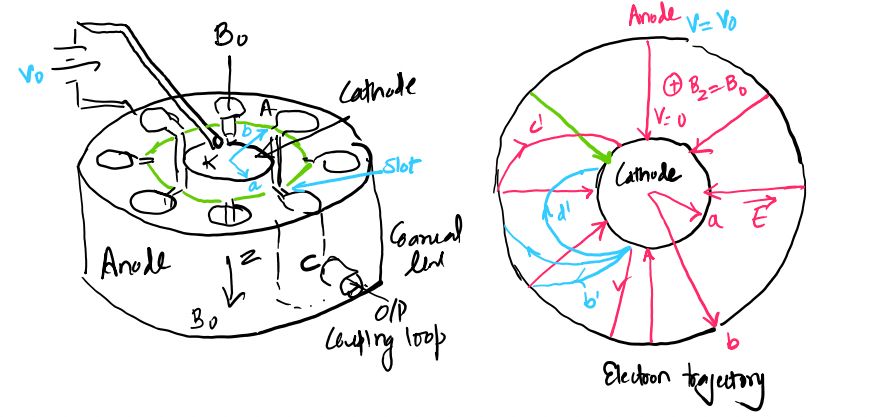
The basic construction of a cavity magnetron consists of a cylindrical cathode placed at the center and a surrounding cylindrical anode block. The cathode is generally a thick cylindrical structure and acts as the source of electrons. The anode is usually made from a highly conductive material such as copper and contains a series of equally spaced slots or re-entrant cavities around its inner circumference. These cavities behave as resonant structures and form the microwave slow-wave system of the magnetron. The region between the cathode and the inner surface of the anode is called the interaction space. This is the region where the emitted electrons interact with the dc electric field, dc magnetic field, and RF electric field. A dc voltage applied between the cathode and anode establishes an approximately radial electric field in the interaction space, while a strong magnetic field is applied along the axis of the cylindrical cathode. The magnetic flux therefore runs parallel to the cathode axis and perpendicular to the radial electric field. The magnetic field may be produced using a permanent magnet or an electromagnet positioned around the magnetron structure. The combination of the central cathode, resonant anode cavities, interaction space, and axial magnetic field forms the basic cross-field arrangement required for magnetron operation.
The resonant cavities in the anode are important because they determine the electromagnetic characteristics of the magnetron and provide the RF fields with which the electrons interact. The slots connecting the cavities to the interaction space allow the RF electric field to fringe out from the cavities into the region between the cathode and anode. When the magnetron starts operating, small RF disturbances or noise voltages can excite the resonant cavity system. The resulting RF electric field interacts with the electrons moving through the crossed-field region. Electrons that are appropriately phased with the RF field are slowed down and transfer part of their kinetic energy to the resonant cavities. This energy transfer causes the RF oscillations to grow. Thus, the anode cavities do not merely provide mechanical slots around the cathode; they form the resonant microwave structure that makes continuous electron-field interaction and microwave power generation possible.
Cross-Field Effect in Cavity Magnetron
The cross-field effect refers to the controlled motion of electrons under the simultaneous influence of mutually perpendicular electric and magnetic fields. In a cavity magnetron, the electric field is directed radially from the anode toward the cathode, while the magnetic field is directed axially along the cathode. Since electrons are negatively charged, the electric field produces a force that tends to move them toward the positive anode. At the same time, the magnetic field produces a force perpendicular to the instantaneous electron velocity, causing the electron trajectory to bend. The total force acting on an electron can be expressed as
\[ \mathbf{F}=-e\left(\mathbf{E}+\mathbf{v}\times\mathbf{B}\right) \]
where \(e\) is the magnitude of the electron charge, \(\mathbf{E}\) is the electric field, \(\mathbf{B}\) is the magnetic flux density, and \(\mathbf{v}\) is the instantaneous electron velocity. The electric and magnetic forces therefore work together to determine the electron trajectory in the interaction space. By adjusting the dc anode voltage and magnetic field, the electron motion can be controlled so that the electrons spend sufficient time travelling around the interaction region and interacting with the RF fields produced by the anode cavities. This is the fundamental cross-field principle that allows the cavity magnetron to convert dc electron energy into microwave RF power.
Electron Motion Under Crossed Electric and Magnetic Fields
The electron trajectory changes significantly according to the strength of the applied magnetic field. When the magnetic field is absent, the electrons are acted upon mainly by the radial electric field and tend to travel directly from the cathode toward the anode. In this condition, the electrons are rapidly collected by the anode and there is little opportunity for the controlled interaction required for efficient magnetron operation. As the magnetic field is increased, the magnetic force bends the electron trajectories and the electrons follow curved paths while moving through the interaction space. The increasing magnetic field causes the electrons to spend more time in the region between the cathode and anode, allowing stronger interaction with the RF fields of the resonant cavities.
At a particular value of magnetic field known as the critical magnetic field or cut-off magnetic field, an electron trajectory just grazes the anode surface without reaching it. The corresponding magnetic flux density is denoted by \(B_c\). When the magnetic field is increased beyond this value, the electrons are prevented from reaching the anode and their trajectories bend back toward the cathode. Therefore, the magnetic field controls whether electrons are collected by the anode or remain within the interaction region. This transition is fundamental to magnetron operation because the useful operating condition requires the electron trajectories to remain controlled within the interaction space so that the electrons can interact with the RF fields and form the electron bunches required for efficient energy transfer.
Basic Operating Concept of a Cavity Magnetron
During operation, the cathode emits electrons into the interaction space, and the dc electric field initially accelerates the electrons toward the anode. The applied axial magnetic field bends their paths, causing them to move along curved trajectories around the cathode instead of travelling directly to the anode. At the same time, small RF oscillations are established in the resonant anode cavities. The RF electric fields extend through the cavity slots into the interaction space and act on the moving electrons. Depending on their position and phase relative to the RF field, some electrons are accelerated while others are retarded. The retarded or favoured electrons lose kinetic energy to the RF field, and this energy increases the amplitude of the cavity oscillations. Electrons that are accelerated by the RF field can move back toward the cathode more rapidly and contribute less to useful RF power generation. The combination of controlled curved electron motion, RF interaction, and electron bunching therefore enables the magnetron to sustain strong microwave oscillations.
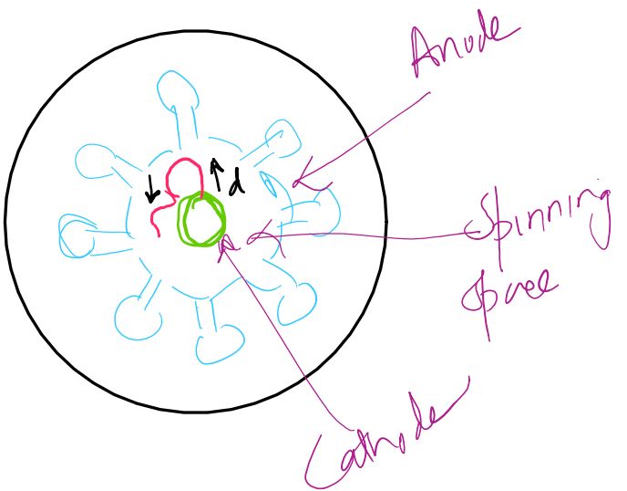
As the operation continues, the RF field produces a phase-focusing action on the electrons. Electrons that are initially emitted at slightly different phases can be influenced by the RF field so that their trajectories become concentrated into groups called electron spokes or electron clouds. These spokes rotate around the cathode and remain synchronized with the RF field in the anode cavities. The electrons within the favoured spokes are gradually retarded and transfer their kinetic energy to the RF oscillations before being collected by the anode. The RF oscillation continues to grow until the energy supplied by the electrons becomes balanced by the losses in the resonant structure and associated circuit. Microwave power can then be extracted from a suitably coupled cavity. In this way, the cavity magnetron functions as a highly efficient cross-field microwave power device.
Importance of the Cross-Field Principle
The cross-field principle is the key feature that distinguishes a cavity magnetron from many other microwave tubes. The perpendicular electric and magnetic fields provide control over the electron trajectory, allowing the electrons to circulate through the interaction space and remain exposed to the RF field for a relatively long interaction period. This extended interaction supports efficient energy transfer from the electron beam to the resonant cavities. The resonant anode cavities further organize the RF field and provide the phase relationship required for electron bunching and sustained oscillation. Because of this combination of crossed-field electron motion and resonant cavity interaction, cavity magnetrons can produce high microwave power and are widely used in applications such as radar transmitters, microwave ovens, and industrial microwave heating systems.
Electron Trajectory, Cut-Off Magnetic Field and Phase Focusing in Cavity Magnetron
The operation of a cavity magnetron depends strongly on the motion of electrons under the combined influence of the radial dc electric field and the axial dc magnetic field. Electrons emitted from the central cathode are attracted toward the positive anode by the electric field, while the magnetic field bends their trajectories and produces a tangential component of motion. The resulting electron path is therefore determined by the relative strengths of the electric and magnetic fields. The force acting on an electron in the interaction space is given by
\[ \mathbf{F}=-e\left(\mathbf{E}+\mathbf{v}\times\mathbf{B}\right) \]
where \(e\) is the magnitude of the electronic charge, \(\mathbf{E}\) is the electric field, \(\mathbf{B}\) is the magnetic flux density, and \(\mathbf{v}\) is the electron velocity. This crossed-field motion is central to the cavity magnetron because the magnetic field prevents the electrons from moving directly to the anode and instead makes them follow curved trajectories through the interaction space. By selecting a suitable combination of anode voltage and magnetic flux density, the electrons can be made to interact effectively with the RF fields of the resonant anode cavities. The electron trajectory therefore determines whether the electrons are collected by the anode, return to the cathode, or remain in the interaction space long enough to transfer energy to the microwave oscillations.
Electron Velocity in the Magnetron
When an electron is emitted from the cathode and accelerated through the dc electric field, it acquires kinetic energy from the applied anode voltage. If the electron starts with negligible initial velocity and is accelerated through a voltage \(V_0\), its initial velocity can be approximated from the conversion of electrical energy into kinetic energy. Thus,
\[ eV_0=\frac{1}{2}mu_0^2 \]
and therefore the electron velocity is
\[ u_0=\sqrt{\frac{2eV_0}{m}} \]
where \(m\) is the electron mass. In the crossed-field region, however, the electron does not continue with a purely radial velocity. The magnetic field acts perpendicular to the instantaneous electron velocity and bends its path, producing both radial and tangential components of motion. The resulting trajectory becomes curved, and the average tangential drift velocity is particularly important for maintaining synchronism between the electron motion and the RF wave travelling around the anode structure.
Electron Trajectory for Different Magnetic Field Strengths
The electron trajectory changes as the magnetic field is increased while the dc anode voltage is kept fixed. Four important operating cases are considered to understand the motion of electrons in a cavity magnetron. These cases show how the magnetic field gradually changes the electron path from direct anode collection to curved motion and finally to trajectories that return toward the cathode.
Case 1: Zero Magnetic Field, \(B=0\)
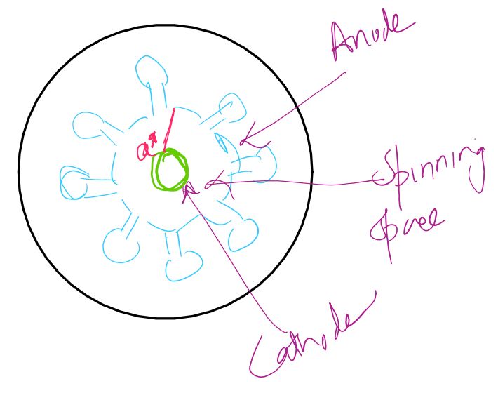
When the magnetic field is absent, the electrons experience the radial electric force without any magnetic deflection. Since the anode is positive with respect to the cathode, the emitted electrons are accelerated directly toward the anode. Their trajectory is approximately a straight radial path from the cathode to the anode. The electrons therefore reach the anode rapidly, producing a large anode current. Because the electrons spend only a short time in the interaction space, the controlled electron-field interaction required for efficient magnetron operation does not occur. This case provides the reference condition for understanding how the magnetic field changes electron motion.
Case 2: Increasing Magnetic Field
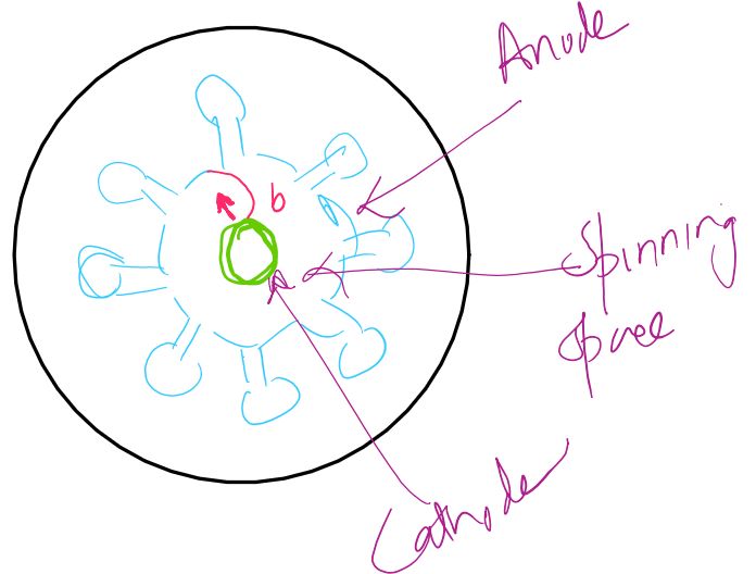
When the magnetic field is gradually increased from zero, a magnetic force acts on the moving electrons in a direction perpendicular to both their velocity and the magnetic field. This force bends the electron trajectories, causing them to follow curved paths instead of travelling directly toward the anode. The electrons consequently spend more time in the interaction space and acquire a significant tangential component of velocity. Once RF oscillations are present in the anode cavities, the RF electric field extending through the cavity slots interacts with these moving electrons. An electron that encounters a retarding RF field loses kinetic energy and transfers that energy to the RF oscillation. Such electrons are referred to as favoured electrons because their motion and phase allow them to contribute useful energy to the microwave field. Their interaction with the RF field is responsible for the formation and strengthening of the electron bunches required for magnetron operation.
Other electrons may encounter the RF field at an unfavorable phase. Instead of losing energy to the RF field, these electrons may gain energy from it. The increased velocity causes their trajectories to bend more strongly under the magnetic field, allowing them to return toward the cathode after spending comparatively little time in the interaction space. These electrons are called unfavoured electrons. They do not contribute effectively to the desired electron bunching and may strike the cathode, producing unwanted heating known as back heating. Thus, the RF field separates electrons according to their phase and causes different groups of electrons to behave differently within the interaction space.
Case 3: Critical Magnetic Field, \(B=B_c\)
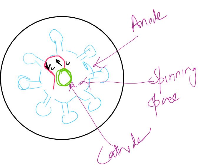
As the magnetic field is increased further, the curvature of the electron trajectory becomes greater. At a particular magnetic flux density, the electron path just grazes the inner surface of the anode without being collected by it. This magnetic field is called the critical magnetic field or cut-off magnetic field, and it is represented by \(B_c\). At this condition, the electron has just enough magnetic deflection to prevent direct anode collection. The corresponding cut-off condition is important in determining the operating region of the magnetron because it establishes the boundary between trajectories that can reach the anode and trajectories that are turned back toward the cathode.
For a cylindrical magnetron having cathode radius \(a\), anode radius \(b\), and dc anode voltage \(V_0\), the Hull cut-off magnetic flux density is given by
\[ B_c= \frac{\sqrt{\frac{8mV_0}{e}}} {b\left(1-\frac{a^2}{b^2}\right)} \]
This equation shows that the cut-off magnetic field depends on the applied anode voltage and the geometry of the cathode-anode structure. For a fixed anode voltage, increasing the magnetic field beyond this critical value prevents electrons from reaching the anode. Conversely, for a fixed magnetic field, the corresponding cut-off voltage can be obtained from the Hull condition.
Case 4: Magnetic Field Greater Than the Critical Value, \(B>B_c\)
When the magnetic field is increased beyond the critical value, the electrons are strongly deflected and their trajectories turn back toward the cathode without reaching the anode. In this condition, the anode current approaches zero for the ideal cut-off condition. The electrons that return to the cathode produce unwanted cathode heating, which is known as back heating. However, in the presence of the RF field, the electron trajectories are modified according to their phase relative to the RF oscillation. Some electrons are accelerated and quickly return toward the cathode, while others are retarded and remain in the interaction region for a longer time. This difference in electron transit time is essential for phase focusing and useful energy transfer to the RF field.
Favoured and Unfavoured Electrons
The RF electric field present across the slots of the resonant anode cavities divides the electrons into groups according to their phase at the time of interaction. Favoured electrons encounter a retarding RF electric field and consequently lose kinetic energy. The lost kinetic energy is transferred to the RF field, causing the cavity oscillations to increase in amplitude. These electrons remain in the interaction space for a comparatively longer time and continue to interact with the RF field as they move around the cathode. Their trajectories are therefore favorable for maintaining the microwave oscillations. In contrast, unfavoured electrons encounter an accelerating RF field and gain kinetic energy. Their increased velocity causes them to move away from the useful interaction condition and return toward the cathode more rapidly. They therefore contribute little or no useful energy to the RF oscillation and can increase cathode heating when they strike the cathode.
Phase Focusing and Electron Bunching
The formation of electron bunches in a cavity magnetron is known as phase focusing. It occurs because the RF electric field modifies the velocity of electrons according to their phase of interaction. Consider an electron that is correctly phased with the RF field and is therefore retarded as it moves through the interaction space. Electrons located slightly ahead or behind this electron experience RF fields that cause their velocities to change in such a way that they move toward the favored electron. An electron on one side of the favored group may be accelerated or retarded relative to the reference electron, while electrons on the other side experience the complementary effect. As a result, electrons initially distributed over a range of phases become concentrated into regions of higher electron density.
These concentrated groups of electrons form electron bunches, commonly called electron spokes in a cavity magnetron. The spokes extend approximately from the cathode toward the anode and rotate around the cathode in synchronism with the RF field pattern established by the resonant cavities. The electrons within the favored spokes experience a retarding RF field and transfer kinetic energy to the cavities. This process strengthens the microwave oscillations. The phase-focusing action therefore performs two important functions: it concentrates electrons into organized bunches and maintains the appropriate phase relationship between the electron motion and the RF field so that energy transfer remains predominantly from the electron beam to the resonant cavity system.
Average Electron Drift Velocity
Although the electrons have both radial and tangential components of velocity while moving through the crossed electric and magnetic fields, their average motion around the cathode can be described by a tangential drift velocity. For the cylindrical magnetron, the average drift velocity is given by
\[ v_{\phi}=\frac{E_r}{B_0} \]
where \(E_r\) is the radial dc electric field and \(B_0\) is the applied dc magnetic flux density. The radial electric field in a cylindrical magnetron varies with radial position and can be expressed as
\[ E(r)= \frac{V_0}{r\ln(b/a)} \]
The drift velocity is important because efficient interaction requires the average electron motion to remain appropriately synchronized with the RF field travelling around the anode cavities. If the electron drift velocity is too low, electrons tend to be deflected toward the anode, while if it is too high, they tend to be deflected toward the cathode. The applied voltage and magnetic field are therefore selected to establish a suitable electron drift condition for efficient interaction with the RF field.
Hull Cut-Off Voltage
The same cut-off condition can also be expressed in terms of voltage. For a given magnetic flux density \(B_0\), the maximum dc voltage at which electrons remain prevented from reaching the anode is described by the Hull cut-off voltage. It is given by
\[ V_c= \frac{e}{8m} B_0^2b^2 \left(1-\frac{a^2}{b^2}\right)^2 \]
Thus, for a given magnetic field, if the applied anode voltage is below the corresponding cut-off value, electrons do not reach the anode under the idealized cut-off condition. The Hull cut-off magnetic field and cut-off voltage are therefore useful for identifying the electron-motion region in which a cavity magnetron can be operated. In practical magnetron design, the operating voltage and magnetic field are selected not merely to prevent anode collection, but also to establish the correct electron drift velocity and phase relationship required for efficient RF energy transfer.
Formation of Electron Spokes
Once the magnetron is operating, the RF electric field in the cavity slots extends into the interaction space and continuously influences the electron trajectories. The phase-focusing effect causes electrons surrounding a favored electron group to converge toward similar phases. These electrons become concentrated into rotating electron clouds or spokes. For the commonly used \(\pi\)-mode operation, the spokes are arranged in a regular pattern around the cathode and rotate in synchronism with the RF field distribution of the anode cavities. As the spokes rotate, electrons within the favored regions encounter a retarding RF field and deliver energy to the resonant cavities. The electrons are subsequently collected by the anode after transferring a portion of their kinetic energy to the RF field.
The electron spokes are therefore not simply stationary bunches of charge. They are rotating groups of electrons whose position and phase are continuously related to the RF field pattern in the anode structure. This rotating interaction allows the magnetron to maintain energy transfer over a substantial portion of the electron trajectory. The combination of crossed-field electron motion, RF velocity modulation, phase focusing, and spoke formation is what enables the cavity magnetron to sustain strong microwave oscillations and operate as a high-power microwave device.
Resonant Cavities, Phase Shift and Magnetron Oscillation in Cavity Magnetron
The anode of a cavity magnetron is designed as a resonant slow-wave structure consisting of a number of equally spaced resonant cavities arranged around the central cathode. These cavities are coupled to one another through the interaction region and their slots allow the RF electric field to extend into the cathode-anode space. When the magnetron is energized, small RF noise voltages can excite the resonant cavity system. Because the cavities are coupled together, the RF field in one cavity influences the field in the adjacent cavities, producing a definite phase relationship between the fields of neighboring cavities. The phase difference between adjacent cavities is one of the most important characteristics of magnetron operation because it determines the mode of oscillation, the direction and phase velocity of the RF field pattern, and the condition required for effective interaction between the rotating electron spokes and the RF field.
Resonant Anode Cavities as a Slow-Wave Structure
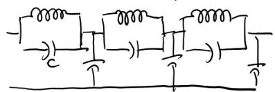
The anode block of a cavity magnetron contains several re-entrant resonant cavities distributed uniformly around its circumference. Each cavity behaves approximately as a resonant circuit having inductive and capacitive effects, while the coupling between neighboring cavities allows an electromagnetic wave to propagate around the closed anode structure. The RF electric field is concentrated mainly across the cavity slots and fringes into the interaction space between the cathode and anode. The alternating RF magnetic field is associated with the resonant cavity structure and is directed approximately along the axis of the magnetron. Since the cavities are coupled and arranged periodically, the anode structure behaves as a slow-wave circuit. The RF field does not simply remain confined to one individual cavity; instead, the coupled cavity system supports different possible field distributions in which adjacent cavities have different phase relationships.
If the magnetron contains \(N\) identical coupled cavities, the closed nature of the anode structure imposes a phase condition on the possible modes of oscillation. After travelling through all \(N\) cavities, the total phase shift must correspond to an integral number of complete cycles. Therefore, the phase shift between adjacent cavities for the \(n\)-th mode is given by
\[ \phi_n=\frac{2\pi n}{N} \]
where \(N\) is the total number of resonant cavities and \(n\) is the mode number. This relationship shows that the possible phase shifts are determined by the number of cavities and the selected resonant mode. Different values of \(n\) produce different phase relationships and therefore different resonant frequencies. The coupled-cavity structure can consequently support several resonant modes, although not all modes are equally suitable for efficient magnetron operation.
Phase Velocity of the RF Field
For effective energy transfer, the rotating RF field established by the coupled cavities must maintain an appropriate relationship with the electron motion. If the phase shift between adjacent cavities is \(\phi\) and the physical distance between adjacent cavity positions along the circular interaction path is \(s\), the phase velocity of the RF wave can be expressed in terms of the phase progression around the anode structure as
\[ v_p=\frac{\omega s}{\phi} \]
where \(\omega\) is the angular frequency of the RF oscillation and \(\phi\) is expressed in radians. The phase velocity describes the speed at which a particular RF phase pattern moves around the interaction space. The electron beam does not need to move at the same physical velocity as the electromagnetic wave in free space. Instead, the magnetron is designed so that the average rotational drift velocity of the electrons is appropriately synchronized with the phase progression of the RF field in the slow-wave structure.
Average Electron Drift Velocity and Synchronism
The electrons emitted from the central cathode move under the combined influence of the radial electric field and axial magnetic field. Although their instantaneous motion contains both radial and tangential components, the average motion around the cathode can be described by the azimuthal drift velocity. For the crossed dc fields, the average drift velocity is approximately
\[ v_{\phi}=\frac{E_r}{B_0} \]
where \(E_r\) is the radial dc electric field and \(B_0\) is the dc magnetic flux density. For a cylindrical magnetron, the radial electric field at radius \(r\) is approximately
\[ E_r=\frac{V_0}{r\ln(b/a)} \]
where \(V_0\) is the dc anode voltage, \(a\) is the cathode radius, and \(b\) is the anode radius. Efficient magnetron operation requires the electron drift motion to remain synchronized with the rotating RF field. If the electron motion is appropriately phased, the electrons in the favored spokes encounter a retarding RF electric field and transfer their kinetic energy to the cavities. The dc anode voltage and magnetic field are therefore adjusted so that the electron drift velocity and RF phase velocity satisfy the required synchronism condition.
Hartree Condition for Magnetron Operation
The condition for strong interaction between the electron beam and the RF field is commonly expressed using the Hartree voltage. For a magnetron operating in a selected mode, the dc anode voltage is adjusted so that the average electron drift velocity is close to the phase velocity of the RF wave in the interaction region. For the commonly used \(\pi\)-mode, the Hartree voltage can be written as
\[ V_{0h} = \frac{2\pi f}{N} \left(b^2-a^2\right)B_0 \]
where \(f\) is the operating frequency, \(N\) is the number of resonant cavities, \(a\) and \(b\) are the cathode and anode radii, and \(B_0\) is the dc magnetic flux density. This condition represents the approximate voltage at which the electron rotational motion is synchronized with the RF field pattern. When the operating conditions are selected close to the required Hartree condition, the electron spokes interact strongly with the retarding RF field and efficient transfer of energy to the resonant cavities takes place.
Mechanism of Magnetron Oscillation
The magnetron oscillation begins with a small RF disturbance, such as noise voltage associated with the dc biasing circuit, exciting one of the allowed resonant modes of the coupled cavity structure. The RF electric field associated with the selected mode extends from the cavity slots into the interaction space. Electrons emitted from the cathode are already moving along curved trajectories because of the crossed dc electric and magnetic fields. As these electrons encounter the RF field, some are accelerated while others are retarded depending on their phase. The retarded electrons lose kinetic energy, and this energy is transferred to the RF field in the resonant cavities. The RF oscillation consequently increases in amplitude.
As the RF field becomes stronger, its interaction with the electrons becomes more effective and produces phase focusing. Electrons that are favorably positioned relative to the RF field become concentrated into rotating electron spokes. The spokes move around the cathode in synchronization with the rotating RF field pattern. Electrons within the favored spokes experience a retarding electric field over a significant part of their trajectory and continuously transfer kinetic energy to the cavity oscillations. The RF field therefore grows until the power delivered by the electrons is balanced by the losses in the cavity structure, coupling system, and other parts of the magnetron. At this point, a steady-state microwave oscillation is established and the generated RF power can be extracted through a suitable output coupling arrangement.
Energy Transfer From Electrons to the RF Field
The essential power-generation process in a cavity magnetron is the conversion of electron kinetic energy into RF energy. The dc electric field supplies energy to the electrons, while the dc magnetic field controls their trajectory and keeps them circulating through the interaction space. The RF field then selectively retards the electrons in the favored phase regions. When an electron is retarded by the RF electric field, its kinetic energy decreases and the corresponding energy is delivered to the electromagnetic field supported by the resonant cavities. Since many electrons are organized into rotating spokes, a large number of electrons can transfer energy coherently to the RF field. This collective energy transfer is what allows the cavity magnetron to generate high microwave power.
The phase shift between adjacent cavities is therefore not merely a characteristic of the resonant structure; it directly affects the relationship between the rotating RF field and the electron spokes. For a specified phase shift such as \(45^\circ\) or \(90^\circ\), the electron drift condition must be selected so that the electrons encounter the appropriate RF phase as they move from one cavity region to the next. In the commonly used \(\pi\)-mode, the \(180^\circ\) phase difference between adjacent cavities creates the strong alternating RF field pattern that is particularly suitable for interaction with the electron spokes. The operating voltage and magnetic field are consequently chosen to establish the required synchronism between the electron motion and the selected RF mode.
Different Resonant Modes in a Cavity Magnetron
A cavity magnetron with \(N\) coupled resonant cavities can support several resonant modes because different phase shifts satisfy the closed-loop condition around the anode structure. Each mode has its own phase relationship and resonant frequency. The general phase-shift equation
\[ \phi_n=\frac{2\pi n}{N} \]
therefore provides the basis for identifying the possible modes. Modes with different values of \(n\) may be close in frequency, which can make unwanted mode excitation a practical problem. In a high-power magnetron, stable operation requires the desired mode to be favored over neighboring modes. This is one reason why practical cavity magnetrons commonly employ mode-control techniques such as strapping, in which metallic straps connect selected anode segments and alter the effective loading of the cavity system. The straps are designed so that the desired \(\pi\)-mode is affected differently from neighboring unwanted modes, increasing the frequency separation between them and improving mode stability.
Sketch a cross-sectional view of a magnetron having 45 degrees of phase shifts among the adjacent cavities, and explain its functioning as a power amplifier.
Phase Shift and Power Amplifier Operation
When a cross-field cavity device is considered as a microwave power amplifier in an examination problem, the essential principle remains the same: the crossed dc electric and magnetic fields control the electron motion, while the resonant cavities establish the RF field and its phase progression. The specified phase shift between adjacent cavities determines the mode of the coupled-cavity structure. An RF signal or RF field associated with the selected cavity mode interacts with the rotating electron spokes, and electrons that encounter the retarding field transfer kinetic energy to the RF field. For a \(45^\circ\) or \(90^\circ\) phase-shift configuration, the cavity fields must maintain the specified phase progression around the anode, while the electron drift velocity is adjusted for effective synchronism. The resulting interaction enables energy from the dc electron beam to reinforce the microwave field and produce high-power RF output.
Working Principle of Cavity Magnetron as a Power Device
The cavity magnetron operates by converting the kinetic energy of electrons into high-power microwave energy through the interaction of an electron cloud with the RF fields of resonant anode cavities. It is a cross-field device in which the dc electric field is radial and the dc magnetic field is axial, so the two fields are perpendicular to each other. The central cathode emits electrons into the interaction space, while the positive anode block surrounding the cathode contains a number of resonant cavities. The dc electric field tends to accelerate the electrons toward the anode, whereas the axial magnetic field bends their trajectories and causes them to move around the cathode along curved paths. When the applied voltage and magnetic field are properly selected, the electrons remain in the interaction space for a sufficiently long period to interact with the RF fields extending from the cavity slots. This extended interaction is the fundamental reason why a magnetron can efficiently convert dc power into microwave RF power.
Establishment of the RF Field
When the magnetron is initially energized, a small RF disturbance or noise voltage is present in the resonant anode structure. Because the anode consists of coupled resonant cavities, this small disturbance can excite one of the natural resonant modes of the cavity system. The resonant cavities develop alternating electric and magnetic fields at the corresponding microwave frequency. The RF electric field is concentrated across the cavity slots and fringes outward from the slots into the interaction space between the cathode and anode. Therefore, the electrons moving through the interaction space are exposed not only to the dc crossed fields but also to the alternating RF electric field associated with the selected cavity mode.
The phase relationship between adjacent cavities determines the spatial distribution of the RF field around the anode. For a specified phase-shift arrangement, such as \(45^\circ\) or \(90^\circ\), the RF field progresses around the cavity structure with the corresponding phase difference between neighboring cavities. In practical magnetrons, the \(\pi\)-mode, having a \(180^\circ\) phase difference between adjacent cavities, is commonly used because it provides strong interaction with the rotating electron spokes. Regardless of the selected mode, the essential operating process is the same: the RF field extends into the interaction space and interacts with electrons whose trajectories are controlled by the crossed dc electric and magnetic fields.
Electron Motion in the Interaction Space
The cathode continuously emits electrons into the interaction space. The radial dc electric field accelerates these electrons toward the anode, while the axial magnetic field produces a force perpendicular to the electron velocity and bends the trajectories. The force acting on an electron is
\[ \mathbf{F}=-e\left(\mathbf{E}+\mathbf{v}\times\mathbf{B}\right) \]
As a result, the electrons do not simply travel radially from the cathode to the anode. Instead, they follow curved trajectories while acquiring a tangential component of velocity. The strength of the magnetic field is selected so that the electrons remain within the interaction space and move around the cathode with an appropriate average drift velocity. This motion allows the electrons to repeatedly encounter the RF fields extending from the resonant cavities. The electron velocity obtained from the dc accelerating voltage, neglecting the initial emission velocity, is approximately
\[ u_0=\sqrt{\frac{2eV_0}{m}} \]
where \(V_0\) is the dc anode voltage, \(e\) is the magnitude of the electron charge, and \(m\) is the electron mass.
Interaction Between Electrons and RF Field
As the electrons move through the interaction space, they encounter the RF electric field at different phases. The RF field may accelerate some electrons and retard others depending on their instantaneous position relative to the cavity field. An electron that encounters a retarding RF electric field loses kinetic energy. The reduction in electron kinetic energy appears as an increase in electromagnetic energy stored in the resonant cavities. Such electrons are called favoured electrons because they provide useful energy to the RF oscillations. On the other hand, electrons encountering an accelerating RF field gain kinetic energy from the RF field and move away from the desired interaction condition. These electrons are called unfavoured electrons and may return toward the cathode, contributing to back heating rather than useful microwave power generation.
The RF field therefore does more than simply exchange energy with individual electrons. It also modifies the velocity and transit time of electrons according to their phase. Electrons that are favorably positioned are retarded and remain in the interaction space for a longer period, while electrons at unfavorable phases can be accelerated and leave the useful interaction region more rapidly. This phase-dependent change in electron velocity is the basis of velocity modulation in the magnetron and leads directly to the formation of electron bunches.
Phase Focusing and Formation of Electron Spokes
The velocity changes produced by the RF electric field cause electrons emitted at different phases to move toward preferred regions of the RF field. This process is known as phase focusing. Electrons that are slightly ahead or behind a favoured electron can experience RF forces that modify their velocities and trajectories so that they become concentrated around the favoured phase. Consequently, the initially distributed electrons form groups of increased electron density called electron bunches or electron spokes.
The electron spokes rotate around the central cathode in synchronism with the RF field pattern established by the coupled anode cavities. The spokes are therefore organized regions of electron charge rather than a random distribution of electrons. Electrons within the favoured spokes encounter the retarding phase of the RF electric field and continuously transfer kinetic energy to the resonant cavity system. The rotating spokes allow the interaction to continue over a significant portion of the electron trajectory, producing an efficient collective interaction between the electron cloud and the microwave field.
Transfer of Electron Energy to the Resonant Cavities
The fundamental power-conversion process in a cavity magnetron occurs when the kinetic energy of the electrons is transferred to the RF field. The dc electric field supplies energy to the electrons as they move away from the cathode, while the dc magnetic field controls their trajectory and keeps them circulating through the interaction region. When the electrons in the favoured spokes encounter the retarding RF field, their kinetic energy decreases. The lost energy is transferred to the electromagnetic oscillations supported by the resonant cavities. Since a large number of electrons participate in the process, the individual energy transfers combine to produce a substantial increase in RF power.
The energy transfer can continue as long as the electron motion remains properly synchronized with the RF field. The dc anode voltage and magnetic flux density are therefore selected to establish an appropriate relationship between the average electron drift velocity and the phase velocity of the RF field. Under the correct operating condition, the electrons encounter the RF field predominantly in a retarding phase and supply energy to the cavity system rather than absorbing it. This synchronized interaction is essential for maintaining high-power microwave oscillations.
Growth of Microwave Oscillations
The oscillation process begins from a small RF disturbance, but the amplitude of the RF field increases as more favoured electrons transfer energy to the resonant cavities. As the RF field becomes stronger, phase focusing becomes more pronounced and the electron spokes become more clearly established. The stronger electron bunches then interact more effectively with the RF field, producing further energy transfer and causing the microwave oscillations to grow. This process continues until the RF power supplied by the electron beam becomes equal to the total power lost in the resonant cavities, output coupling system, and other resistive and practical losses.
At steady state, the cavity magnetron does not continue increasing its RF amplitude indefinitely. Instead, the energy supplied by the electrons balances the losses associated with the microwave circuit and output load. A stable microwave oscillation is then maintained at the selected resonant frequency and mode. The steady-state condition can therefore be described conceptually as a balance between the RF power delivered by the electron beam and the total RF losses of the magnetron system.
Microwave Power Extraction
Once stable RF oscillations have been established, the generated microwave energy is extracted from the resonant cavity structure through a suitable coupling mechanism. An external coupling loop, probe, or other output-coupling arrangement can be associated with an appropriate cavity to transfer part of the electromagnetic energy to an external transmission line or waveguide. The coupling must be designed so that sufficient microwave power is delivered to the load while maintaining stable oscillation inside the magnetron. The extracted RF power can then be supplied to a microwave system such as a radar transmitter, industrial heating system, or microwave oven.
Complete Working Sequence of Cavity Magnetron
The complete working process of a cavity magnetron can be understood as a continuous sequence of electron emission, crossed-field motion, RF interaction, phase focusing, electron bunching, energy transfer, and microwave power extraction. First, the heated central cathode emits electrons into the interaction space. The applied dc electric field accelerates the electrons toward the anode, while the axial dc magnetic field bends their trajectories and produces controlled curved motion around the cathode. Small RF noise excites a resonant mode of the coupled anode cavities, producing RF electric fields that fringe through the cavity slots into the interaction space. As the electrons pass through these RF fields, some electrons are retarded and transfer kinetic energy to the RF field, while others are accelerated and become unfavoured electrons. The RF interaction changes the electron velocities and produces phase focusing, causing electrons to concentrate into rotating spokes. The favoured electrons within these spokes encounter the retarding RF field and continuously deliver energy to the resonant cavities. The RF oscillations consequently grow until the energy delivered by the electrons is balanced by the RF losses and output power being extracted. A stable high-power microwave oscillation is then maintained and coupled out to the external microwave circuit.
Cavity Magnetron as a Cross-Field Microwave Power Device
The cavity magnetron is therefore a cross-field microwave power device in which the dc electric field, dc magnetic field, electron motion, and resonant cavity fields work together. The electric field supplies energy to the electrons, the magnetic field controls their trajectory, the resonant cavities establish the microwave field, and phase focusing organizes the electrons into spokes that transfer energy efficiently to the RF oscillations. The ability of the electron cloud to interact with the RF field over a comparatively long path is one of the main reasons for the high power capability and efficiency of the magnetron. The same operating principle applies when analyzing examination problems involving specified phase shifts between adjacent cavities. For a \(45^\circ\) or \(90^\circ\) phase-shift configuration, the cavity fields follow the specified phase progression, while the electron trajectories and drift conditions are adjusted so that the electron spokes remain synchronized with the RF field and transfer energy to the cavity system.
A cavity magnetron is designed to generate high microwave power by transferring the kinetic energy of electrons to the RF fields supported by the resonant anode cavities. Its high-power capability, comparatively high efficiency, and ability to operate at microwave frequencies make it particularly useful in radar transmitters, microwave ovens, and industrial heating systems. The practical performance of a magnetron depends on the dc anode voltage, magnetic flux density, resonant cavity structure, operating mode, electron phase focusing, and the efficiency with which RF energy is coupled to the external load. Unlike many microwave amplifier tubes, the conventional cavity magnetron is primarily a self-excited microwave oscillator, although examination questions may describe a cross-field cavity device in the context of microwave power amplification. The important practical aspects of cavity magnetron operation include the selection and stabilization of the desired resonant mode, separation of unwanted modes, frequency tuning, RF power extraction, and maintaining the required balance between electron-delivered RF power and circuit losses.
Power Output and Efficiency of Cavity Magnetron
The cavity magnetron is capable of producing very high microwave power because a large number of electrons can interact collectively with the RF field through rotating electron spokes. The dc supply provides energy to the electron cloud, while the crossed electric and magnetic fields control the electron trajectories and keep the electrons in the interaction space for effective RF interaction. When the favoured electrons encounter the retarding RF field, they transfer part of their kinetic energy to the resonant cavities. A practical magnetron can therefore deliver substantial microwave power while maintaining relatively high conversion efficiency. Representative high-power magnetron specifications include peak output powers reaching tens of megawatts in pulsed operation, while average power can reach hundreds of kilowatts in suitable high-power systems. Commercial magnetrons are also available at much lower power levels for applications such as microwave heating. Typical magnetron efficiency is approximately 40% to 70%, although the actual value depends on the particular design, operating condition, frequency, loading, and power level.
The efficiency of a cavity magnetron can be understood from the conversion of dc electron-beam power into RF output power. If \(P_{\mathrm{dc}}\) is the dc input power and \(P_{\mathrm{RF}}\) is the useful microwave output power, the conversion efficiency is expressed as
\[ \eta= \frac{P_{\mathrm{RF}}}{P_{\mathrm{dc}}}\times100\% \]
The high efficiency of the magnetron results from the fact that the electron beam interacts with the RF field over a relatively long curved trajectory and that phase focusing concentrates the electrons into spokes that transfer energy coherently to the cavity fields. The actual output power is obtained through an external coupling arrangement connected to one of the resonant cavities, with the coupling designed to transfer the required amount of RF energy to the load without excessively disturbing the oscillation condition.
Resonant Modes in a Cavity Magnetron
A cavity magnetron containing \(N\) coupled resonant cavities can support several different resonant modes. Each mode is characterized by a particular phase difference between adjacent cavities and has a corresponding resonant frequency. The general phase shift between adjacent cavities is given by
\[ \phi_n= \frac{2\pi n}{N} \]
where \(n\) is the mode number and \(N\) is the number of resonant cavities. Because the anode structure is closed on itself, the total phase shift around the complete circumference must be an integral multiple of \(2\pi\). Consequently, only certain phase relationships can exist as natural modes of the coupled cavity system. The different modes generally have slightly different resonant frequencies, and several of these frequencies may lie close to one another. This small frequency separation can make the magnetron susceptible to unwanted mode oscillation or mode jumping. A practical magnetron therefore requires a method of separating the desired operating mode from neighboring modes.
Sketch a cross-sectional view of a magnetron having 45 degrees of phase shifts among the adjacent cavities, and explain its functioning as a power amplifier.
45 Degree Phase Shift Between Adjacent Cavities
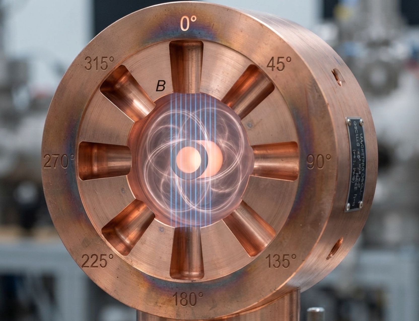
For a cavity magnetron specified to have a \(45^\circ\) phase shift between adjacent cavities, the RF field in each successive cavity differs in phase by \(45^\circ\) from the field in the preceding cavity. Since \(45^\circ=\pi/4\) radians, the mode condition becomes
\[ \phi_n= \frac{2\pi n}{N} = \frac{\pi}{4} \]
Therefore,
\[ \frac{n}{N} = \frac{1}{8} \]
For the simplest case \(n=1\), the corresponding closed structure requires eight equal phase steps around one complete \(360^\circ\) cycle. The phase sequence can be represented as \(0^\circ\), \(45^\circ\), \(90^\circ\), \(135^\circ\), \(180^\circ\), \(225^\circ\), \(270^\circ\), and \(315^\circ\), before returning to \(360^\circ\), which is equivalent to \(0^\circ\). In an examination sketch, the central cylindrical cathode should be shown with the resonant anode cavities arranged around it, together with the interaction space and the applied axial magnetic field. The adjacent cavities should then be marked with the successive \(45^\circ\) phase progression. If a larger number of physical cavities is used, the same \(45^\circ\) phase difference corresponds to the appropriate mode number satisfying \(n=N/8\).
Design and describe the working principle of a cross field cavity device for power amplifier. Consider a 90° phase shift between adjacent cavities.
90 Degree Phase Shift Between Adjacent Cavities
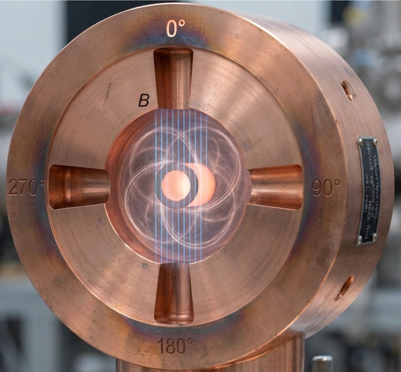
For a \(90^\circ\) phase shift between adjacent cavities, the RF field changes by one quarter of a cycle from one cavity to the next. The mode condition is
\[ \phi_n= \frac{2\pi n}{N} = \frac{\pi}{2} \]
and hence
\[ \frac{n}{N} = \frac{1}{4} \]
For the simplest case with \(n=1\), four equal phase steps complete one full \(360^\circ\) phase cycle. The cavity phases can therefore be represented as \(0^\circ\), \(90^\circ\), \(180^\circ\), and \(270^\circ\), followed by \(360^\circ\), which is equivalent to \(0^\circ\). For an examination question asking for a cross-field cavity device with a \(90^\circ\) phase shift, the sketch should clearly show the cylindrical cathode, surrounding resonant cavities, interaction space, radial electric field, axial magnetic field, and the \(90^\circ\) phase progression between adjacent cavity fields. The electron trajectories should be shown as curved paths around the cathode, indicating the cross-field interaction responsible for transferring electron energy to the RF field.
| Parameter | \(45^{\circ }\) Phase Shift Mode | \(90^{\circ }\) Phase Shift Mode |
|---|---|---|
| Phase Shift (\(\phi _{n}\)) | \(45^{\circ }\) (\(\pi/4\) radians) | \(90^{\circ }\) (\(\pi/2\) radians) |
| Cavity Ratio (\(n/N\)) | \(\frac{n}{N}=\frac{1}{8}\) | \(\frac{n}{N}=\frac{1}{4}\) |
| Mode Equation Condition | \(\phi _{n}=\frac{2\pi n}{N}=\frac{\pi }{4}\) | \(\phi _{n}=\frac{2\pi n}{N}=\frac{\pi }{2}\) |
| Minimum Cavities (\(N\)) for \(n=1\) | 8 cavities | 4 cavities |
| Phase Sequence | \(0^\circ, 45^\circ, 90^\circ, 135^\circ, 180^\circ, 225^\circ, 270^\circ, 315^\circ\) | \(0^\circ, 90^\circ, 180^\circ, 270^\circ\) |
Mode Separation Using Straps
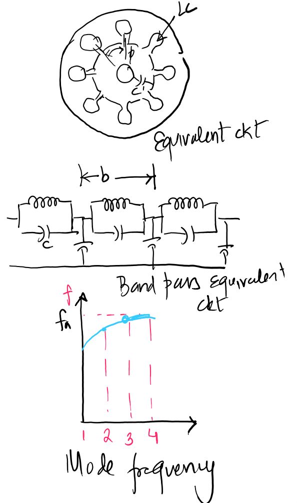
The different resonant modes of a cavity magnetron can have closely spaced frequencies, making it possible for the device to jump from the desired operating mode to an unwanted neighboring mode. Such mode jumping is undesirable because it can change the operating frequency and reduce the stability of the microwave output. To improve mode separation, practical magnetrons commonly use strapping. In the strapping arrangement, metallic rings or straps are connected alternately to the even-numbered and odd-numbered anode segments. The straps are designed so that the desired \(\pi\)-mode experiences a different electrical effect from the neighboring modes. For the \(\pi\)-mode, adjacent anode segments are at opposite RF potentials, so each strap group can remain approximately at a common potential. Consequently, the desired mode experiences capacitive loading that lowers its resonant frequency. For neighboring modes, there is a phase difference between successive strap connection points, producing current in the straps and an associated inductive effect. This shifts the unwanted-mode frequencies upward. The result is an increased frequency separation between the desired \(\pi\)-mode and the adjacent unwanted modes, improving mode stability.
Frequency Tuning of Cavity Magnetron
The operating frequency of a cavity magnetron is primarily determined by the resonant characteristics of its anode cavities. Fine frequency adjustment can be achieved by changing the effective capacitance associated with the resonant cavity system. One practical method is to use a tuning ring, often called a C-ring, positioned near the anode structure and the strap arrangement. The tuning ring introduces additional capacitance into the resonant circuit. Since increasing capacitance lowers the resonant frequency of a resonant circuit, changing the position or effective coupling of the tuning ring allows the operating frequency to be adjusted over a limited range. The tuning arrangement is therefore useful for fine frequency adjustment after the basic magnetron dimensions and cavity structure have established the nominal operating frequency.
\[ f_0= \frac{1}{2\pi\sqrt{LC}} \]
where \(L\) and \(C\) represent the effective inductance and capacitance of the resonant cavity system. From this relationship, an increase in effective capacitance produces a reduction in resonant frequency. The tuning ring is therefore useful for fine adjustment of the selected magnetron mode while the strapping arrangement primarily provides mode separation and stability.
Advantages of Cavity Magnetron
The cavity magnetron has several important advantages as a high-power microwave source. Its crossed-field structure provides strong interaction between the electron cloud and the RF field, allowing efficient conversion of dc power into microwave power. It can generate very high peak RF power while maintaining relatively high efficiency compared with many other microwave vacuum devices. The construction is comparatively compact for the amount of microwave power produced, and the device can operate as a self-excited oscillator without requiring a separate RF drive source. Magnetrons are also capable of operating at commonly used microwave frequencies and can provide substantial continuous-wave or pulsed power depending on their construction. These characteristics make them particularly attractive for high-power applications in which efficiency, power capability, and relatively simple microwave generation are important.
Limitations of Cavity Magnetron
Despite its high power and efficiency, a cavity magnetron has limitations. Its frequency stability is generally poorer than that of highly controlled microwave oscillators because the operating frequency can be affected by changes in anode voltage, magnetic field, temperature, load conditions, and cavity characteristics. The presence of several closely spaced resonant modes can also lead to mode competition and mode jumping if adequate mode separation is not provided. Strapping and other mode-control techniques are therefore important in practical designs. The output frequency is not normally controlled with the same precision as in many modern solid-state or specialized frequency-source systems, and the conventional cavity magnetron is primarily a power oscillator rather than a linear microwave amplifier. In addition, high-power operation requires suitable magnetic-field generation, thermal management, high-voltage insulation, and reliable RF output coupling.
Applications of Cavity Magnetron
Cavity magnetrons are widely used wherever high microwave power is required. One of their most important applications is in radar transmitters, where the magnetron generates high-power microwave pulses in the GHz frequency range for transmission through the radar antenna. The high peak-power capability of the magnetron makes it suitable for radar systems that require strong transmitted pulses. Magnetrons are also extensively used in microwave ovens, where a magnetron converts electrical energy into microwave energy for heating food. Common domestic microwave ovens operate at frequencies such as \(915\,\mathrm{MHz}\) or \(2.45\,\mathrm{GHz}\), with \(2.45\,\mathrm{GHz}\) being widely used in domestic equipment. In industrial microwave heating, magnetrons provide microwave power for heating, drying, processing, and other material-treatment applications. Depending on the system, industrial magnetrons can provide power ranging from kilowatts upward. Their high efficiency and ability to generate substantial microwave power make them useful in these heating applications.