PG, Available Gain and Transducer Gain Numerical 1
1. Problem Statement
A silicon bipolar junction transistor has the following scattering parameters at 1 GHz with a reference impedance of \(50\,\Omega\):
\[ S_{11}=0.38\angle -158^\circ \]
\[ S_{12}=0.11\angle 54^\circ \]
\[ S_{21}=3.50\angle 80^\circ \]
\[ S_{22}=0.40\angle -43^\circ \]
Note: Caluclator storing trick 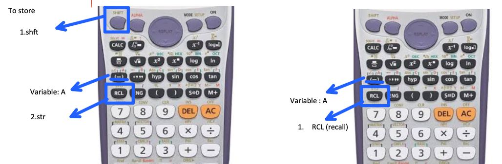

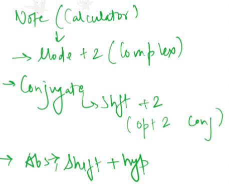
The source impedance and load impedance are given as
\[ Z_S=25\,\Omega \]
\[ Z_L=40\,\Omega \]
Determine the operating power gain \(G_P\), available power gain \(G_A\), and transducer power gain \(G_T\). Also determine the total gain \(G_PG_AG_T\) in linear form and convert \(G_P\), \(G_A\), \(G_T\), and the total gain into decibels. Perform the calculation for both the bilateral and unilateral cases.
In microwave amplifier design, S-parameters provide a convenient method for analyzing transistor performance at high frequencies. The three important gain quantities, namely operating power gain, available power gain, and transducer power gain, describe different aspects of power transfer through the amplifier. Since the given transistor has a non-zero reverse transmission coefficient \(S_{12}\), the complete calculation initially considers the transistor as a bilateral device. The unilateral case is then obtained by assuming \(S_{12}=0\), allowing the effect of reverse transmission on the calculated gain to be observed.
2. Calculation of Source and Load Reflection Coefficients
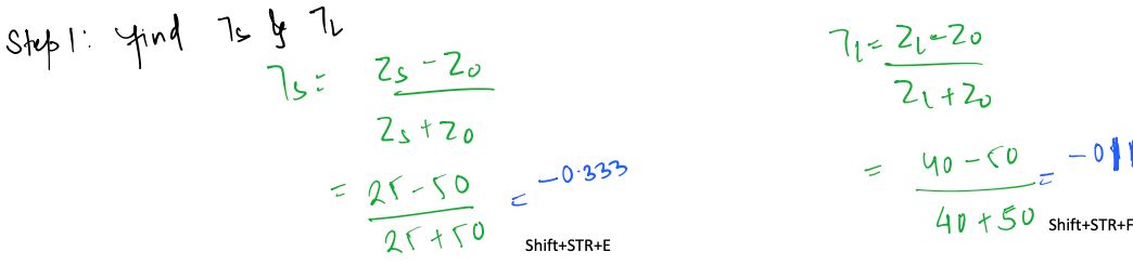
The source reflection coefficient is calculated from the source impedance and reference impedance using
\[ \Gamma_S=\frac{Z_S-Z_0}{Z_S+Z_0} \]
\[ \Gamma_S=\frac{25-50}{25+50} \]
\[ \Gamma_S=-0.333 \]
Similarly, the load reflection coefficient is
\[ \Gamma_L=\frac{Z_L-Z_0}{Z_L+Z_0} \]
\[ \Gamma_L=\frac{40-50}{40+50} \]
\[ \Gamma_L=-0.111 \]
3. Bilateral Amplifier Gain
For the bilateral case, the complete set of S-parameters is used, including the non-zero reverse transmission coefficient \(S_{12}\). Therefore, both the source and load can influence the opposite port through the internal reverse transmission of the transistor.
3.1 Bilateral Input Reflection Coefficient
The input reflection coefficient is calculated using
\[ \Gamma_{in} = S_{11} + \frac{S_{12}S_{21}\Gamma_L} {1-S_{22}\Gamma_L} \]
Substituting the given S-parameters and \(\Gamma_L=-0.111\), we obtain
\[ \Gamma_{in}=0.365\angle -152^\circ \]
Thus, the effective input reflection coefficient of the bilateral transistor is approximately \(0.365\angle -152^\circ\).

3.2 Bilateral Output Reflection Coefficient
The output reflection coefficient is given by
\[ \Gamma_{out} = S_{22} + \frac{S_{12}S_{21}\Gamma_S} {1-S_{11}\Gamma_S} \]
Substituting the given values gives
\[ \Gamma_{out}=0.545\angle -43^\circ \]

3.3 Bilateral Operating Power Gain
The operating power gain is defined as the ratio of the power delivered to the load to the power delivered to the input of the two-port network. It is given by
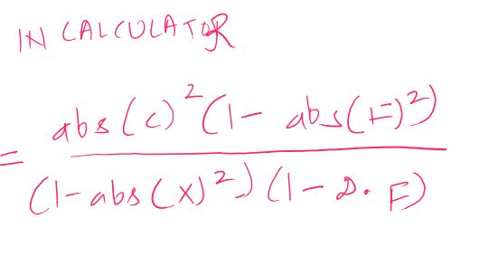
\[ G_P= \frac{|S_{21}|^2(1-|\Gamma_L|^2)} {(1-|\Gamma_{in}|^2)|1-S_{22}\Gamma_L|^2} \]
Substituting the calculated values gives
\[ G_P= \frac{|S_{21}|^2(1-|\Gamma_L|^2)} {(1-|\Gamma_{in}|^2)|1-S_{22}\Gamma_L|^2} \]
\[ G_P=13.1 \]
Therefore, the bilateral operating power gain is
\[ \boxed{G_P=13.1} \]
3.4 Bilateral Available Power Gain
The available power gain is given by
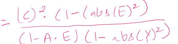
\[ G_A= \frac{|S_{21}|^2(1-|\Gamma_S|^2)} {|1-S_{11}\Gamma_S|^2(1-|\Gamma_{out}|^2)} \]
Substituting the calculated values gives
\[ G_A= \frac{|S_{21}|^2(1-|\Gamma_S|^2)} {|1-S_{11}\Gamma_S|^2(1-|\Gamma_{out}|^2)} \]
\[ G_A=19.8 \]
Therefore, the bilateral available power gain is
\[ \boxed{G_A=19.8} \]
3.5 Bilateral Transducer Power Gain
The transducer power gain takes both source and load mismatches into account and is given by
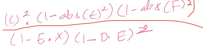
\[ G_T= \frac{ |S_{21}|^2 (1-|\Gamma_S|^2) (1-|\Gamma_L|^2) }{ |1-\Gamma_S\Gamma_{in}|^2 |1-S_{22}\Gamma_L|^2 } \]
Substituting the calculated values gives
\[ G_T= \frac{ |S_{21}|^2 (1-|\Gamma_S|^2) (1-|\Gamma_L|^2) }{ |1-\Gamma_S\Gamma_{in}|^2 |1-S_{22}\Gamma_L|^2 } \]
\[ G_T=12.6 \]
Therefore, the bilateral transducer power gain is
\[ \boxed{G_T=12.6} \]
4. Bilateral Total Gain
For the requested total gain, the three calculated gain quantities are multiplied together. Thus, the total bilateral gain in linear form is
\[ G_{\text{Total,B}} = G_PG_AG_T \]
\[ G_{\text{Total,B}} = 13.1\times19.8\times12.6 \]
\[ \boxed{G_{\text{Total,B}}\approx3271.5} \]
To express the individual gains in decibels, the power-gain conversion is
\[ G_{\mathrm{dB}}=10\log_{10}(G) \]
Therefore, the bilateral operating power gain in decibels is
\[ G_{P,\mathrm{dB}} = 10\log_{10}(13.1) \approx11.17\,\mathrm{dB} \]
The bilateral available power gain in decibels is
\[ G_{A,\mathrm{dB}} = 10\log_{10}(19.8) \approx12.97\,\mathrm{dB} \]
The bilateral transducer power gain in decibels is
\[ G_{T,\mathrm{dB}} = 10\log_{10}(12.6) \approx11.00\,\mathrm{dB} \]
The total gain in decibels can be obtained by adding the three individual gains in decibels:
\[ G_{\text{Total,B(dB)}} = G_{P,\mathrm{dB}} + G_{A,\mathrm{dB}} + G_{T,\mathrm{dB}} \]
\[ G_{\text{Total,B(dB)}} = 11.17+12.97+11.00 \]
\[ \boxed{G_{\text{Total,B(dB)}}\approx35.14\,\mathrm{dB}} \]
This is consistent with the linear total gain because
\[ 10\log_{10}(G_{\text{Total,B}}) = 10\log_{10}(G_PG_AG_T) \]
\[ = 10\log_{10}(G_P) + 10\log_{10}(G_A) + 10\log_{10}(G_T) \]
5. Unilateral Amplifier Gain
For the unilateral case, the reverse transmission coefficient is assumed to be zero. Therefore,
\[ S_{12}=0 \]
With this assumption, the input and output reflection coefficients become independent of the opposite termination. From the general input reflection coefficient,
\[ \Gamma_{in} = S_{11} + \frac{S_{12}S_{21}\Gamma_L} {1-S_{22}\Gamma_L} \]
\[ \boxed{\Gamma_{in}=S_{11}} \]
Similarly, the output reflection coefficient becomes
\[ \Gamma_{out} = S_{22} + \frac{S_{12}S_{21}\Gamma_S} {1-S_{11}\Gamma_S} \]
\[ \boxed{\Gamma_{out}=S_{22}} \]
5.1 Unilateral Operating Power Gain
For the unilateral amplifier, \(\Gamma_{in}=S_{11}\). Therefore, the operating power gain becomes
\[ G_{PU} = \frac{ |S_{21}|^2(1-|\Gamma_L|^2) }{ (1-|S_{11}|^2) |1-S_{22}\Gamma_L|^2 } \]
Substituting the given values gives
\[ G_{PU}\approx13.25 \]
\[ \boxed{G_{PU}\approx13.25} \]
The corresponding value in decibels is
\[ G_{PU,\mathrm{dB}} = 10\log_{10}(13.25) \]
\[ \boxed{G_{PU,\mathrm{dB}}\approx11.22\,\mathrm{dB}} \]
5.2 Unilateral Available Power Gain
For a unilateral amplifier, \(\Gamma_{out}=S_{22}\). Therefore, the available power gain becomes
\[ G_{AU} = \frac{ |S_{21}|^2(1-|\Gamma_S|^2) }{ |1-S_{11}\Gamma_S|^2 (1-|S_{22}|^2) } \]
Substituting the given values gives
\[ G_{AU}\approx16.59 \]
\[ \boxed{G_{AU}\approx16.59} \]
Converting this value into decibels gives
\[ G_{AU,\mathrm{dB}} = 10\log_{10}(16.59) \]
\[ \boxed{G_{AU,\mathrm{dB}}\approx12.20\,\mathrm{dB}} \]
5.3 Unilateral Transducer Power Gain
The unilateral transducer power gain is obtained by setting \(S_{12}=0\) in the general transducer gain expression. It becomes
\[ G_{TU} = \frac{ |S_{21}|^2 (1-|\Gamma_S|^2) (1-|\Gamma_L|^2) }{ |1-S_{11}\Gamma_S|^2 |1-S_{22}\Gamma_L|^2 } \]
Substituting the given values gives
\[ G_{TU}\approx12.90 \]
\[ \boxed{G_{TU}\approx12.90} \]
The corresponding gain in decibels is
\[ G_{TU,\mathrm{dB}} = 10\log_{10}(12.90) \]
\[ \boxed{G_{TU,\mathrm{dB}}\approx11.11\,\mathrm{dB}} \]
6. Unilateral Total Gain
The requested total unilateral gain is obtained by multiplying the unilateral operating power gain, available power gain, and transducer power gain:
\[ G_{\text{Total,U}} = G_{PU}G_{AU}G_{TU} \]
\[ G_{\text{Total,U}} = 13.25\times16.59\times12.90 \]
\[ \boxed{G_{\text{Total,U}}\approx2837.7} \]
The total unilateral gain in decibels is obtained by adding the individual unilateral gain values in decibels:
\[ G_{\text{Total,U(dB)}} = G_{PU,\mathrm{dB}} + G_{AU,\mathrm{dB}} + G_{TU,\mathrm{dB}} \]
\[ G_{\text{Total,U(dB)}} = 11.22+12.20+11.11 \]
\[ \boxed{G_{\text{Total,U(dB)}}\approx34.53\,\mathrm{dB}} \]
The same result is obtained directly from the linear total gain using
\[ 10\log_{10}(G_{\text{Total,U}}) = 10\log_{10}(G_{PU}G_{AU}G_{TU}) \]
7. Comparison of Bilateral and Unilateral Gain
The calculated results can be compared by considering the complete bilateral model and the unilateral approximation in which \(S_{12}\) is neglected. In the bilateral case, the non-zero \(S_{12}\) causes the source and load terminations to influence the opposite ports through reverse transmission. In the unilateral case, this feedback path is removed by setting \(S_{12}=0\), which changes the effective input and output reflection coefficients and consequently changes the calculated gain values.
| Gain Parameter | Bilateral | Bilateral (dB) | Unilateral | Unilateral (dB) |
|---|---|---|---|---|
| Operating Power Gain \(G_P\) | 13.1 | 11.17 dB | 13.25 | 11.22 dB |
| Available Power Gain \(G_A\) | 19.8 | 12.97 dB | 16.59 | 12.20 dB |
| Transducer Power Gain \(G_T\) | 12.6 | 11.00 dB | 12.90 | 11.11 dB |
| Total Gain \(G_PG_AG_T\) | 3271.5 | 35.14 dB | 2837.7 | 34.53 dB |
8. Final Results
For the complete bilateral amplifier, the operating power gain is approximately \(13.1\), the available power gain is approximately \(19.8\), and the transducer power gain is approximately \(12.6\). Their corresponding decibel values are approximately \(11.17\,\mathrm{dB}\), \(12.97\,\mathrm{dB}\), and \(11.00\,\mathrm{dB}\), respectively. The requested product of the three gains is approximately \(3271.5\), corresponding to approximately \(35.14\,\mathrm{dB}\).
For the unilateral approximation with \(S_{12}=0\), the operating power gain is approximately \(13.25\), the available power gain is approximately \(16.59\), and the transducer power gain is approximately \(12.90\). Their corresponding decibel values are approximately \(11.22\,\mathrm{dB}\), \(12.20\,\mathrm{dB}\), and \(11.11\,\mathrm{dB}\). The requested product of the three unilateral gains is approximately \(2837.7\), corresponding to approximately \(34.53\,\mathrm{dB}\).