Single Stage Microwave Transistor Amplifier
Single Stage Microwave Transistor Amplifier and Transducer Power Gain
1. Single Stage Microwave Transistor Amplifier
A single-stage microwave transistor amplifier is a basic microwave circuit in which one transistor stage is used to amplify an input signal and deliver the amplified power to a load. At microwave frequencies, the transistor cannot usually be connected directly between the source and load because the source and load impedances may not provide the required power transfer or amplifier response. Therefore, input and output matching circuits are commonly placed around the transistor. The input matching circuit transforms the source impedance into the appropriate impedance presented to the transistor, while the output matching circuit transforms the load impedance to the impedance required at the transistor output. In this way, the matching networks and transistor work together to obtain the desired overall amplifier response.
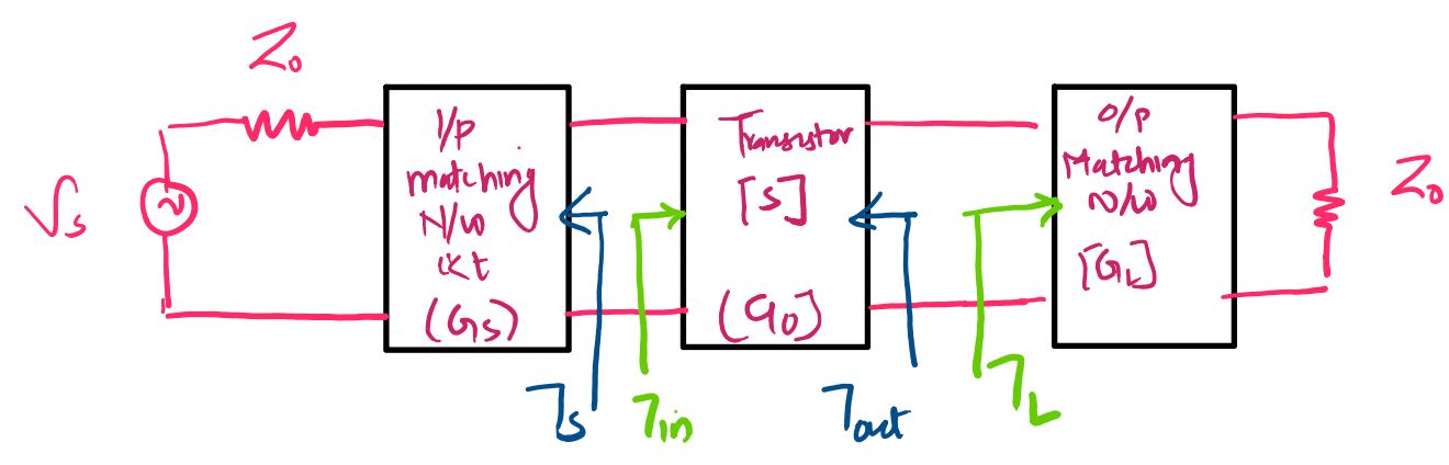
The single-stage amplifier can therefore be viewed as three functional sections: the input or source matching network, the microwave transistor, and the output or load matching network. Each section contributes to the transfer of available source power toward the load. Using scattering parameters, the effect of these sections can be represented conveniently through effective gain factors. These gain factors allow the overall transducer power gain of the amplifier to be expressed in a compact form without requiring a lengthy derivation of the complete amplifier network.
1.1 Input and Output Matching in a Single Stage Amplifier
The input matching circuit is connected between the microwave source and the transistor input. Its purpose is to transform the source impedance into a suitable impedance for the transistor so that the available source power can be transferred effectively into the amplifier. The source reflection coefficient is represented by \(\Gamma_S\), while the input reflection coefficient looking into the transistor is represented by \(\Gamma_{in}\). The interaction between these two reflection coefficients determines the effective gain associated with the input matching network.
Similarly, the output matching circuit is connected between the transistor output and the load. It transforms the load impedance into an appropriate impedance at the transistor output, allowing power to be transferred efficiently from the transistor to the load. The load reflection coefficient is represented by \(\Gamma_L\), and the transistor output behavior is described using its scattering parameters. For the unilateral case, the output reflection coefficient of the transistor is determined directly by \(S_{22}\).
Because microwave transistor amplifiers operate with complex impedances and reflected waves, impedance matching is an important part of the overall amplifier design. The matching networks do not simply increase the intrinsic transistor gain; instead, they control how effectively power is accepted from the source and delivered to the load. This is why the overall amplifier gain can be described using separate source, transistor, and load gain factors.
1.2 Effective Gain Factors
The overall behavior of the single-stage microwave transistor amplifier can be represented using three effective gain factors. The first factor is the source gain \(G_S\), which represents the effect of the input matching network. The second is the transistor gain \(G_0\), which represents the forward power transfer characteristic of the transistor. The third is the load gain \(G_L\), which represents the effect of the output matching network on power delivered to the load.
For a unilateral transistor, where the reverse transmission parameter \(S_{12}\) is zero or sufficiently small to be neglected, the input and output behavior becomes independent. In this case, the input reflection coefficient can be written as \(\Gamma_{in}=S_{11}\), while the output reflection coefficient is represented by \(S_{22}\). The three gain factors can then be written directly in terms of the transistor S-parameters and the source and load reflection coefficients.
1.2.1 Source Gain
The source gain \(G_S\) represents the effective power transfer associated with the input matching network. It depends on the source reflection coefficient \(\Gamma_S\) and the input reflection coefficient of the transistor. For the unilateral transistor model, \(\Gamma_{in}=S_{11}\), giving the following expression:
\[ G_S = \frac{1-\left|\Gamma_S\right|^2}{\left|1-S_{11}\Gamma_S\right|^2} \]
The numerator \(1-\left|\Gamma_S\right|^2\) represents the fraction of available source power that can be delivered according to the source reflection coefficient, while the denominator accounts for the interaction between the source and the input reflection coefficient of the transistor. Thus, \(G_S\) indicates how the input matching condition affects the amount of source power that is effectively accepted by the transistor.
1.2.2 Transistor Gain
The intrinsic forward gain contribution of the transistor is represented by \(G_0\). In terms of the forward scattering parameter \(S_{21}\), the transistor gain factor is given by:
\[ G_0 = \left|S_{21}\right|^2 \]
The parameter \(S_{21}\) describes the forward transmission characteristic of the transistor, relating the output wave to the input wave under the standard S-parameter conditions. Therefore, \(\left|S_{21}\right|^2\) represents the corresponding power transmission factor. A larger magnitude of \(S_{21}\) indicates a stronger forward power transfer through the transistor and therefore a larger contribution to the overall amplifier gain.
1.2.3 Load Gain
The load gain \(G_L\) represents the effective power transfer associated with the output matching network. It depends on the load reflection coefficient \(\Gamma_L\) and the transistor output reflection behavior. For the unilateral transistor model, the output behavior is determined by \(S_{22}\), so the load gain is written as:
\[ G_L = \frac{1-\left|\Gamma_L\right|^2}{\left|1-S_{22}\Gamma_L\right|^2} \]
The numerator \(1-\left|\Gamma_L\right|^2\) represents the fraction of power associated with the load reflection condition, while the denominator accounts for the interaction between the transistor output and the load. Consequently, the value of \(G_L\) depends on how the output matching network transforms the load and how closely the resulting impedance condition is suited to the transistor output.
2. Transducer Power Gain of a Single-Stage Amplifier
The performance of a single-stage microwave transistor amplifier is commonly described using the transducer power gain \(G_T\). Transducer power gain is defined as the ratio of the power delivered to the load to the power available from the source. It therefore describes the overall ability of the amplifier system, including its matching networks and transistor, to transfer available source power into the load.
\[ G_T=\frac{\text{Power Delivered to Load}}{\text{Power Available from Source}} \]
For the single-stage amplifier model, the overall transducer power gain can be represented by the product of the source gain, transistor gain, and load gain. Therefore, the overall gain is:
\[ G_T = G_S G_0 G_L \]
This expression provides a convenient way to understand the gain contribution of each section of the amplifier. \(G_S\) represents the effect of the input matching network, \(G_0\) represents the forward gain contribution of the transistor, and \(G_L\) represents the effect of the output matching network. The product of these three factors gives the overall transducer power gain of the single-stage amplifier.
3. Unilateral Transistor Model
In practical microwave transistor analysis, the reverse transmission parameter \(S_{12}\) may sometimes be sufficiently small that its effect can be neglected. When \(S_{12}=0\), or when it is small enough to justify the unilateral approximation, the transistor is treated as a unilateral transistor. This approximation simplifies the analysis because a signal traveling from the output back toward the input is considered negligible.
Under the unilateral condition, the input reflection coefficient is independent of the load and is given by:
\[ \Gamma_{in}=S_{11} \]
Likewise, the output reflection behavior is determined by \(S_{22}\), giving:
\[ \Gamma_{out}=S_{22} \]
Because of this simplification, the source and load matching conditions can be considered separately when analyzing the amplifier. The unilateral transducer power gain is consequently expressed as the product of the three effective gain factors:
\[ G_{TU}=G_S G_0 G_L \]
For the unilateral microwave transistor amplifier, the three factors are therefore:
\[ G_S = \frac{1-\left|\Gamma_S\right|^2}{\left|1-S_{11}\Gamma_S\right|^2} \]
\[ G_0 = \left|S_{21}\right|^2 \]
\[ G_L = \frac{1-\left|\Gamma_L\right|^2}{\left|1-S_{22}\Gamma_L\right|^2} \]
These equations provide the basic gain model for a single-stage unilateral microwave transistor amplifier. The source gain describes the input-side power transfer, the transistor gain describes the forward power transmission through the active device, and the load gain describes the output-side power transfer. Their product gives the unilateral transducer power gain, making this model particularly useful for analyzing and designing microwave amplifiers using measured or specified S-parameters.
4. Overall Gain Relationship
The single-stage microwave transistor amplifier can therefore be understood as a combination of an input matching network, an active transistor, and an output matching network. The matching networks transform the source and load impedances into suitable impedances for the transistor, while the transistor provides the forward amplification. For the unilateral model, the overall transducer gain is conveniently expressed through the three individual gain factors.
\[ G_{TU} = \left( \frac{1-\left|\Gamma_S\right|^2} {\left|1-S_{11}\Gamma_S\right|^2} \right) \left|S_{21}\right|^2 \left( \frac{1-\left|\Gamma_L\right|^2} {\left|1-S_{22}\Gamma_L\right|^2} \right) \]
This relationship shows directly how the source matching condition, transistor forward transmission, and load matching condition combine to determine the power gain of the complete amplifier. It is therefore a fundamental expression for the analysis of a single-stage unilateral microwave transistor amplifier, particularly when the transistor is characterized by its S-parameters at the operating frequency.