Traveling Wave Tube (TWT)
Introduction, Bunching Effect and Construction of Traveling Wave Tube (TWT)
The Traveling Wave Tube (TWT) is one of the most versatile and widely used microwave vacuum tubes for RF and microwave amplification. Unlike cavity-based microwave tubes such as klystrons, which rely on discrete resonant cavities for electron interaction, a TWT uses a continuous interaction structure that allows energy transfer between an electron beam and an electromagnetic wave over the entire length of the tube. Because of this distributed interaction mechanism, the Traveling Wave Tube provides very high gain, low noise performance, and extremely wide bandwidth, making it one of the most important microwave amplifiers used in radar systems, satellite communication, troposcatter links, communication repeaters, and electronic warfare systems. TWTs are commonly designed for operation over frequencies ranging from approximately 0.3 GHz to 50 GHz, while practical devices can operate from about 0.5 GHz to 95 GHz depending on the design and application requirements.
What is Bunching Effect?
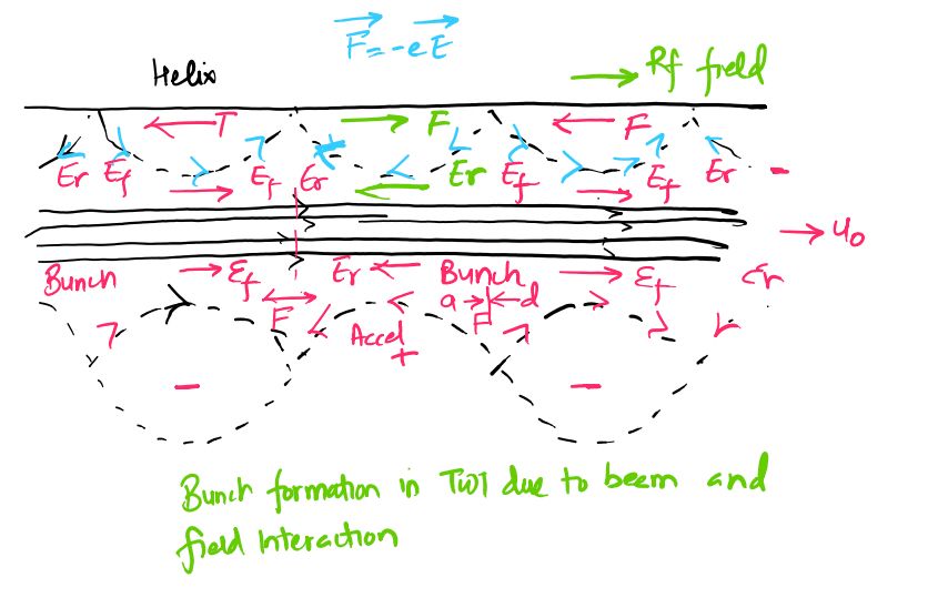
The bunching effect is the process by which electrons in an electron beam are grouped into clusters or bunches due to differences in their velocities. Initially, electrons emitted from the cathode travel with nearly uniform velocity and are distributed uniformly along the beam. When the beam interacts with an RF electric field, some electrons are accelerated while others are decelerated depending on the phase of the RF signal encountered by each electron. As the faster electrons catch up with the slower electrons during transit, the electrons begin to gather into compact groups known as electron bunches. This process is called electron bunching or density modulation. Bunching is extremely important because it enables efficient transfer of kinetic energy from the electron beam to the RF electromagnetic wave. As the bunches move through the tube, they continuously reinforce the microwave signal, causing amplification. Without electron bunching, efficient microwave amplification would not be possible in a Traveling Wave Tube.
Is TWT an Amplifier or an Oscillator?
A Traveling Wave Tube is primarily designed and operated as a microwave amplifier. The device receives a microwave signal at its input, amplifies the signal through continuous interaction between the electron beam and the traveling RF wave, and delivers a larger signal at the output. Unlike oscillators, a standard TWT does not generate microwave energy independently because it does not contain the positive feedback necessary for self-sustained oscillations. However, if an external feedback path is intentionally introduced between the output and input sections, the device can be configured to operate as a Traveling Wave Tube Oscillator (TWTO). In practical microwave communication and radar systems, TWTs are overwhelmingly used as high-gain broadband amplifiers because their wide bandwidth and large power capability make them exceptionally suitable for amplification applications.
Construction of Traveling Wave Tube (TWT)
The physical structure of a Traveling Wave Tube consists of an electron gun assembly, a slow-wave interaction structure, a focusing system, an attenuator section, RF coupling arrangements, and a collector electrode, all enclosed within a vacuum envelope. The electron gun is located at one end of the tube and consists primarily of a heated cathode and anode arrangement. The cathode emits electrons through thermionic emission, and the anode accelerates these electrons to form a narrow, high-velocity electron beam directed along the central axis of the tube. Surrounding the interaction region is a magnetic focusing system that produces an axial magnetic field to keep the electron beam tightly confined and prevent beam spreading during transit. Permanent magnets are commonly used in low-power TWTs, while high-power TWTs employ solenoid electromagnets to provide stronger focusing fields.
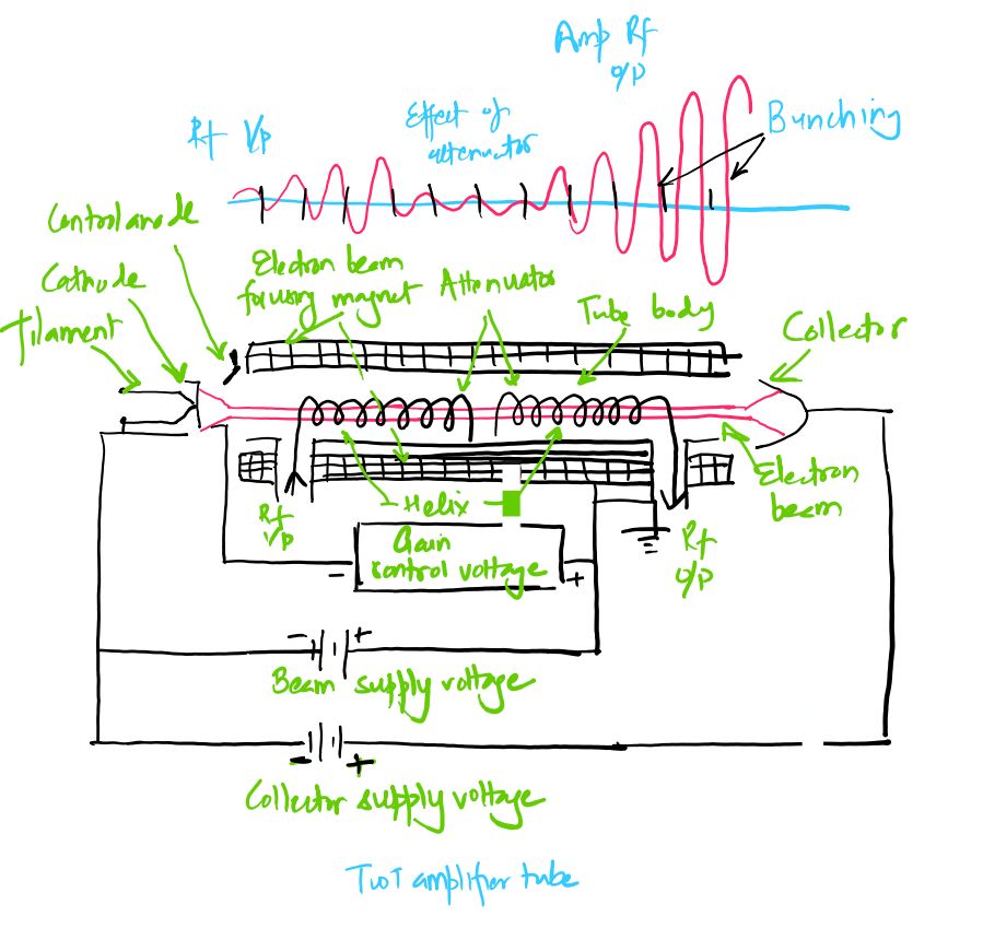
The most important component of the TWT is the helical slow-wave structure positioned along the path of the electron beam. This helix is a spiral conductor that acts as a non-resonant transmission line for microwave energy. The RF input signal is coupled into one end of the helix through an input coupler, while the amplified signal is extracted from the opposite end through an output coupler. Although the electromagnetic wave travels along the helix conductor at approximately the speed of light, the spiral geometry forces the wave to follow a much longer path than the electron beam. As a result, the axial phase velocity of the RF wave is greatly reduced. This slowing action allows the RF wave to travel at nearly the same speed as the electron beam, thereby maintaining continuous interaction between the two throughout the entire length of the tube.
An attenuator is usually inserted around the middle section of the helix. The purpose of this attenuator is to absorb reflected waves caused by impedance mismatches and prevent those reflections from propagating back toward the input section. Without the attenuator, reflected signals could establish feedback and cause unwanted oscillations. The attenuator suppresses the reflected waves while allowing the electron beam to continue traveling unaffected through the interaction region. At the far end of the tube, the collector captures the electrons after they have transferred a significant portion of their kinetic energy to the RF signal. The collector safely dissipates the remaining electron energy and completes the operation of the device.
Working Principle Based on BeamWave Interaction
The operation of a Traveling Wave Tube begins when a microwave signal is applied to the input end of the helix and an electron beam is emitted from the cathode. The helix slows the propagation of the RF wave so that its axial phase velocity becomes approximately equal to the velocity of the electron beam. As both the electron beam and the RF wave travel together along the tube, the longitudinal electric field associated with the RF signal interacts continuously with the electrons. Electrons encountering accelerating portions of the field gain velocity, while those encountering retarding portions lose velocity. This velocity modulation gradually develops into density modulation as faster electrons catch up with slower electrons, creating compact electron bunches. The bunches move along the tube in synchronism with the RF wave and continuously transfer kinetic energy to the electromagnetic field. As more energy is transferred from the electron beam to the RF signal, the amplitude of the microwave wave grows progressively larger along the length of the helix.
Because the interaction occurs continuously rather than at discrete cavity locations, the Traveling Wave Tube can provide very high gain over an exceptionally wide frequency range. The amplified microwave signal is extracted from the output end of the helix near the collector. The resulting output power is significantly greater than the input power, thereby achieving microwave amplification. This continuous beam-wave interaction process, together with the bunching effect and the slow-wave structure, forms the fundamental operating principle of the Traveling Wave Tube amplifier.
Working Principle of Traveling Wave Tube (TWT)
The Traveling Wave Tube (TWT) operates on the principle of continuous interaction between an electron beam and a traveling microwave signal propagating through a slow-wave structure. Unlike cavity-type microwave tubes, where energy exchange occurs only at specific cavity locations, a TWT allows interaction to take place continuously throughout the entire length of the tube. This continuous beam-wave interaction is responsible for the exceptionally high gain and wide bandwidth characteristics of the TWT. The amplification process begins when an electron beam generated by the electron gun is accelerated by the anode and directed along the axis of the tube. Simultaneously, a microwave signal is coupled into one end of the helical slow-wave structure. The purpose of the helix is to reduce the axial phase velocity of the electromagnetic wave so that it becomes nearly equal to the velocity of the electron beam. This synchronization is essential because efficient energy transfer can occur only when the electrons and the RF wave travel together for a significant distance.
Electron-Beam Generation and RF Signal Injection
The electron gun produces a focused stream of electrons through thermionic emission from the cathode. The emitted electrons are accelerated by the electric field established between the cathode and anode, resulting in a high-velocity electron beam traveling toward the collector. A static magnetic field produced by permanent magnets or electromagnetic solenoids surrounds the interaction region and keeps the beam tightly focused. At the same time, the microwave input signal is injected into the helix through an input directional coupler. The electromagnetic wave travels along the helical conductor at nearly the speed of light, but because the wave must follow the spiral path of the helix, its effective axial phase velocity is greatly reduced. The helix therefore acts as a slow-wave structure that enables the RF wave and electron beam to remain synchronized throughout the interaction region.
Synchronization of the RF Wave and Electron Beam
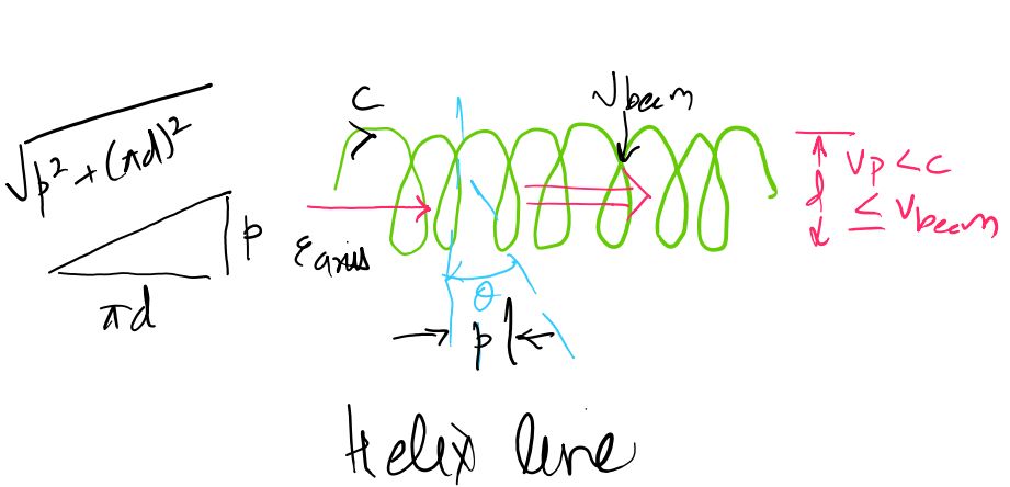
For effective amplification, the velocity of the electron beam is adjusted to be slightly greater than the phase velocity of the RF wave traveling along the helix. Under this condition, the electrons repeatedly encounter alternating accelerating and decelerating regions of the longitudinal electric field associated with the microwave signal. If the electron velocity were much higher than the wave velocity, interaction time would be too short and amplification would be negligible. Similarly, if the wave moved faster than the electrons, the wave would outrun the beam and efficient energy transfer could not occur. The carefully controlled synchronization between beam velocity and wave phase velocity therefore forms the foundation of TWT operation.
Beam–Field Interaction, Velocity Modulation and Density Modulation
As the microwave signal propagates along the helix, it produces a longitudinal electric field component inside the helix structure. This field alternately accelerates and decelerates electrons depending on the phase of the RF signal encountered by each electron. Electrons passing through accelerating regions gain velocity, while electrons entering decelerating regions lose velocity. Some electrons pass through regions where the electric field is nearly zero and therefore retain their original velocity. This variation in electron velocity is known as velocity modulation. As the beam continues to travel along the tube, the faster electrons begin catching up with slower electrons, causing the electrons to gather into compact groups. This process transforms velocity modulation into density modulation, producing electron bunches that correspond to the frequency of the input microwave signal.
Progressive Bunching and Energy Transfer
The bunching process becomes progressively stronger as the electrons move farther along the interaction region. Since the electron beam velocity is maintained slightly greater than the phase velocity of the RF wave, more electrons encounter retarding electric fields than accelerating electric fields. Consequently, a larger fraction of the beam kinetic energy is transferred to the electromagnetic wave than is received from it. The electron bunches therefore lose kinetic energy while the amplitude of the traveling RF wave continuously increases. The amplified wave then produces stronger electric fields, which in turn create tighter electron bunches and further increase energy transfer. This regenerative interaction continues throughout the length of the helix and results in substantial amplification of the microwave signal before the electrons finally reach the collector.
Continuous Amplification Along the Helix
A unique feature of the Traveling Wave Tube is that amplification occurs continuously rather than at discrete locations. In cavity devices such as klystrons, energy exchange takes place only when electrons pass through cavity gaps. In a TWT, however, every section of the helix contributes to amplification. As the electromagnetic wave progresses along the slow-wave structure, it continuously receives energy from successive electron bunches. The signal therefore grows gradually and continuously along the interaction region. When the power transferred from the electron beam compensates for the losses within the system, a stable and amplified microwave signal appears at the output end of the tube. Because this interaction extends over the entire tube length, TWTs can achieve high gain while maintaining a very wide operating bandwidth.
Role of the Attenuator and Prevention of Oscillations
An attenuator is positioned approximately midway along the helix to suppress reflected waves that may arise because of impedance mismatches at the output section. If these reflected waves were allowed to propagate back toward the input, they could establish an unwanted feedback path and convert the amplifier into an oscillator. The attenuator absorbs both forward and reflected RF waves in the attenuated region without significantly affecting the electron beam. After passing through the attenuator, the electron bunches continue to interact with the regenerated forward wave and amplification proceeds normally. The attenuator therefore plays a crucial role in maintaining stable amplifier operation while preventing self-oscillation.
Extraction of the Amplified RF Output
Near the collector end of the tube, the traveling RF wave has accumulated a large amount of energy transferred from the electron beam. The amplified microwave signal is extracted through an output directional coupler connected to the end of the helix. After transferring much of their kinetic energy to the RF wave, the electrons are collected by the collector electrode and removed from the interaction process. The output signal possesses the same frequency as the input signal but with a significantly larger amplitude and power level. This ability to provide high gain over an extremely wide frequency range makes the Traveling Wave Tube one of the most important microwave amplifiers used in radar, satellite communications, electronic warfare, and long-distance communication systems.
Operating Sequence of a Traveling Wave Tube
Electron Beam Generation
        ↓
RF Wave Injection
        ↓
Velocity Modulation
        ↓
Density Modulation
        ↓
Electron Bunching
        ↓
Energy Transfer to RF Wave
        ↓
Progressive Amplification
        ↓
Amplified Microwave Output
Helix Slow-Wave Structure and Wave Propagation Analysis
One of the most important features responsible for the successful operation of a Traveling Wave Tube (TWT) is the helix slow-wave structure. In a normal transmission medium, electromagnetic waves propagate at a velocity very close to the speed of light. If such a high propagation velocity were maintained inside the tube, the microwave signal would quickly outrun the electron beam, resulting in very little interaction between the electrons and the RF field. Since efficient microwave amplification requires prolonged interaction between the electron beam and the electromagnetic wave, the wave velocity must be reduced to a value approximately equal to the electron-beam velocity. This requirement is fulfilled by the helix slow-wave structure. The helical conductor forces the RF signal to travel along a spiral path rather than a straight path, increasing the actual distance travelled by the wave and thereby reducing its effective axial phase velocity. As a result, the RF wave and the electron beam remain synchronized over a long interaction distance, allowing continuous energy transfer from the electron beam to the microwave signal.
Need for Slow-Wave Structures
The velocity of an electron beam produced inside a TWT is much lower than the speed of light. If the microwave signal propagated directly along the tube axis at the speed of light, the electromagnetic wave would pass the electrons almost instantly and there would be insufficient interaction to produce amplification. Therefore, a structure capable of slowing the propagation of the RF wave is required. Such a structure is known as a slow-wave structure. The helix is the most widely used slow-wave structure because it provides a broad operating bandwidth, excellent beam-wave interaction, simple construction, and smooth propagation characteristics over a wide frequency range. By reducing the phase velocity of the RF signal to a value comparable to the electron-beam velocity, the helix ensures that the wave and electron bunches travel together throughout the length of the tube, making continuous amplification possible.
Helix Geometry and Physical Structure
The helix consists of a conducting wire wound into a spiral shape around the electron-beam axis. The geometry of the helix is primarily determined by two parameters: the helix pitch and the helix diameter. The pitch, usually represented by p, is the axial distance between adjacent turns of the helix. The diameter, represented by d, determines the circumference of each turn. As the microwave signal propagates along the helical conductor, it follows the spiral path of the wire rather than moving directly along the tube axis. Consequently, the signal must travel a much greater distance than the electrons, which move almost straight toward the collector. This increased path length is responsible for the reduction in the axial phase velocity of the electromagnetic wave. By carefully selecting the helix pitch and diameter, engineers can design the slow-wave structure so that the RF wave velocity closely matches the electron-beam velocity for maximum amplification.
Axial Electric Field and Beam-Wave Synchronization
As the microwave signal travels along the helix, an axial electric field component is produced inside the structure. This longitudinal electric field is extremely important because it directly interacts with the electrons moving along the axis of the tube. Portions of the field accelerate certain electrons while other portions decelerate them, producing velocity modulation. The resulting velocity differences gradually transform into density modulation and electron bunching. For this interaction to remain effective throughout the tube, the phase velocity of the RF wave must remain approximately equal to the velocity of the electron beam. This condition is known as synchronization. When synchronization is achieved, the electron bunches continuously encounter retarding electric fields and transfer kinetic energy to the traveling wave, causing the RF signal amplitude to increase progressively along the helix.
Wave Propagation in the Helix
Although the electromagnetic wave propagates along the helical conductor at approximately the speed of light, its axial movement along the tube is much slower because of the spiral geometry. Consider a helix having pitch p and diameter d. During one complete turn, the wave travels along the helical wire through a distance equal to the length of the spiral turn, while advancing only by the pitch distance in the axial direction. The travel time along the wire and the corresponding axial travel time must be equal. Using the geometry of the helix, the axial phase velocity of the RF wave can therefore be derived as:
\[ v_p=\frac{cp}{\sqrt{(\pi d)^2+p^2}} \]
where \(v_p\) is the axial phase velocity of the wave, \(c\) is the speed of light, \(p\) is the helix pitch, and \(d\) is the helix diameter. This expression shows that the axial phase velocity is always less than the speed of light because the denominator is greater than the pitch. Thus, the helical geometry naturally slows the RF wave and enables synchronization with the electron beam.
Practical Approximation of Phase Velocity
In most practical Traveling Wave Tubes, the helix pitch is much smaller than the helix circumference, that is, \(p \ll \pi d\). Under this condition, the term \(p^2\) in the denominator becomes negligible compared with \((\pi d)^2\). Therefore, the phase-velocity equation can be simplified considerably to obtain a useful design approximation:
\[ v_p \approx \frac{cp}{\pi d} \]
This simplified relationship clearly illustrates how the geometry of the helix controls wave velocity. Increasing the helix pitch increases the phase velocity because the wave advances farther in the axial direction during each turn. Conversely, increasing the helix diameter increases the circumference of the spiral path and therefore decreases the axial phase velocity. Engineers use this relationship extensively during TWT design to obtain the required synchronization between the RF wave and the electron beam.
Effect of Helix Dimensions on TWT Performance
The dimensions of the helix strongly influence the gain, bandwidth, efficiency, and operating frequency range of the Traveling Wave Tube. A smaller pitch reduces the phase velocity and strengthens beam-wave interaction, while a larger pitch increases phase velocity and may reduce synchronization efficiency. Similarly, increasing the helix diameter lowers the phase velocity and improves interaction but may introduce mechanical and manufacturing limitations. Proper selection of helix dimensions ensures that the electron beam remains slightly faster than the traveling RF wave, which is the ideal condition for efficient energy transfer and microwave amplification. Because the helix provides a continuously distributed interaction region rather than discrete resonant cavities, it allows the TWT to achieve very wide bandwidth while maintaining high gain and stable operation.
Design Significance of the Helix Slow-Wave Structure
The helix slow-wave structure is the key component that distinguishes a Traveling Wave Tube from other microwave vacuum tubes. By reducing the phase velocity of the RF wave and maintaining synchronization with the electron beam, it enables continuous beam-wave interaction over the entire length of the tube. This continuous interaction results in progressive electron bunching, efficient energy transfer, high gain, and exceptionally wide bandwidth. The ability to control phase velocity through simple geometric parameters such as pitch and diameter makes the helix an extremely versatile slow-wave structure for microwave amplification. Consequently, the helix slow-wave structure forms the foundation of modern TWT design and is largely responsible for the tube's widespread use in satellite communication systems, radar transmitters, electronic warfare equipment, and broadband microwave communication networks.
Performance Characteristics, Distortion and Noise in Traveling Wave Tubes
The Traveling Wave Tube (TWT) is widely regarded as one of the most versatile microwave amplifiers because it combines high gain, wide bandwidth, and substantial power-handling capability within a single device. Unlike resonant cavity microwave amplifiers whose operation is confined to relatively narrow frequency ranges, the TWT employs a non-resonant helix slow-wave structure that allows efficient amplification over a broad spectrum of frequencies. This characteristic makes TWTs indispensable in satellite communications, radar systems, electronic warfare equipment, troposcatter links, and broadband microwave communication networks. The practical performance of a TWT is evaluated using parameters such as frequency range, bandwidth, gain, efficiency, output power capability, distortion characteristics, and noise performance. Although TWTs offer exceptional amplification and bandwidth advantages, practical limitations such as heat generation, nonlinearity near saturation, and efficiency constraints must also be considered during system design.
Frequency Range and Bandwidth
One of the most important advantages of a Traveling Wave Tube is its extremely wide operating frequency range. Conventional microwave vacuum tubes often achieve high gain at the expense of bandwidth because their operation depends upon resonant cavities tuned to specific frequencies. In contrast, the helix slow-wave structure used in a TWT is essentially non-resonant and supports traveling-wave interaction over a broad range of frequencies. Commercial TWTs are available for operation from approximately 0.3 GHz to 50 GHz, while specialized designs can extend the operating range up to about 95 GHz. Because the interaction mechanism does not rely on sharply tuned resonators, the usable bandwidth of a TWT is generally greater than one octave, making it suitable for wideband communication systems where large frequency coverage is required without frequent retuning.
Output Power Capability and Modes of Operation
Traveling Wave Tubes are available in a wide variety of power ratings ranging from low-power laboratory and communication amplifiers to extremely high-power radar transmitters. Low-power TWTs operating in the higher microwave frequency bands typically provide output powers of approximately 5 mW. Medium-power and high-power designs can produce significantly greater output levels, with continuous-wave (CW) TWTs delivering power outputs up to approximately 250 kW at frequencies around 3 GHz. In pulsed operation, where energy is delivered in short-duration bursts, peak power outputs can reach approximately 10 MW. The ability to operate in both continuous-wave and pulsed modes gives TWTs remarkable flexibility for communication and radar applications. Continuous-wave operation is commonly used in satellite communications and long-distance communication links, whereas pulsed operation is widely employed in radar transmitters where very high peak power is required.
Gain Characteristics of a Traveling Wave Tube
A major reason for the widespread use of TWTs is their ability to provide very high power gain. Because the electron beam and electromagnetic wave interact continuously throughout the entire length of the slow-wave structure, amplification occurs progressively rather than at isolated cavity locations. This distributed interaction mechanism allows gains greater than 40 dB and, in many practical systems, gains approaching 60 dB. Initially, the gain remains nearly constant as the input signal level increases. In this region, known as the small-signal or linear operating region, the output signal increases proportionally with the input signal. The TWT therefore behaves as an approximately linear amplifier and reproduces the input waveform with minimal distortion. This operating region is preferred in communication systems where signal fidelity is important.
Saturation Effects
As the RF input power continues to increase, the amplification process eventually approaches a limit known as saturation. In the saturation region, the electron beam has already transferred a substantial portion of its kinetic energy to the traveling electromagnetic wave, leaving less energy available for further amplification. Consequently, the output power no longer increases proportionally with the input power. Instead, the gain begins to decrease and eventually reaches a point where additional increases in input power produce little or no increase in output power. The operating point corresponding to the maximum output power is called the saturation point, and the gain at this condition is referred to as the saturation gain. Although operation near saturation maximizes output power, it also introduces significant nonlinear effects and distortion.
Efficiency of a Traveling Wave Tube
The efficiency of a TWT is defined as the ratio of RF output power to the dc power supplied to the electron beam. Although the continuous beam-wave interaction mechanism provides high gain and wide bandwidth, it does not achieve very high efficiency compared with some cavity-type microwave tubes. Practical TWT efficiencies generally lie in the range of approximately 5% to 20%, depending on operating frequency, beam voltage, power level, and tube design. Several factors contribute to this moderate efficiency. The internal attenuator absorbs some RF energy, heat is generated due to conductor losses in the helix, and not all electron kinetic energy can be converted into useful microwave power. Nevertheless, the combination of wide bandwidth and high gain often outweighs the efficiency limitations in many practical systems.
Harmonic Distortion and Intermodulation Distortion
When a TWT operates near saturation, electron bunching becomes increasingly intense and nonlinear. The resulting beam current contains sharp peaks that are rich in harmonic frequency components. These harmonics appear at integer multiples of the fundamental frequency and constitute harmonic distortion. Such distortion can degrade signal quality and may require filtering at the amplifier output. Another important form of nonlinearity is intermodulation distortion, which occurs when multiple frequencies are amplified simultaneously. Because the transfer characteristic becomes nonlinear near saturation, unwanted sum and difference frequency components are generated. Intermodulation distortion is particularly important in communication systems carrying multiple channels because it can create interference between signals and reduce overall system performance.
Phase Distortion
In addition to amplitude-related distortions, TWTs can also exhibit phase distortion. At higher operating levels, where a larger fraction of electron-beam energy is converted into RF power, the average beam velocity decreases. This reduction in beam velocity alters the propagation delay through the tube and produces a corresponding phase shift at the output. As the phase shift varies with input power level, unwanted conversion between amplitude and phase variations can occur. In communication systems using phase-sensitive modulation techniques, such phase distortion may significantly affect signal integrity and therefore must be carefully controlled or compensated.
Noise Generation and Noise Figure
Noise performance is another important consideration in Traveling Wave Tube operation. Noise originates primarily from fluctuations in cathode emission, variations in electron velocity, and random interactions within the electron beam. Despite being a vacuum electronic device, a TWT can exhibit relatively good noise performance when designed for low-noise applications. Specialized low-noise TWTs may achieve noise figures below 10 dB and are therefore suitable for microwave receiver front-end applications. Medium-power TWTs typically exhibit noise figures in the range of approximately 18 dB to 30 dB, while high-power TWTs generally have noise figures between approximately 24 dB and 27 dB. The noise characteristics determine the suitability of a particular TWT for receiver or transmitter applications.
Heat Dissipation and Cooling Requirements
The amplification process within a TWT generates a considerable amount of heat due to beam power losses, conductor losses in the helix, and energy absorbed by the internal attenuator. Effective heat removal is therefore essential for reliable operation. Low-power TWTs may rely on natural or forced-air cooling, whereas high-power systems frequently require sophisticated liquid-cooling arrangements. The need for cooling equipment increases system complexity, size, and operating cost. Heat dissipation limitations also impose practical restrictions on the maximum power that can be obtained from single-helix TWT designs because excessive temperatures can damage the helix structure and reduce tube lifetime.
Practical Limitations of Helix TWTs
Although helix TWTs provide outstanding gain and bandwidth performance, several practical limitations exist. The helix structure is mechanically delicate and can be difficult to manufacture for very high-power applications. The internal attenuator, while necessary to suppress oscillations, reduces overall gain and efficiency. Heat generated within the helix imposes limitations on maximum continuous output power and requires elaborate cooling systems in high-power installations. Operation near saturation introduces harmonic distortion, intermodulation distortion, and phase distortion that can degrade signal quality. Furthermore, the moderate efficiency of TWTs means that a significant portion of the supplied electrical power is converted into heat rather than useful RF output. Despite these limitations, the unique combination of high gain, exceptionally wide bandwidth, and broad frequency coverage ensures that Traveling Wave Tubes remain indispensable components in many advanced microwave systems.
Typical Performance Characteristics of Traveling Wave Tubes
- Frequency Range: Approximately 0.3 GHz to 95 GHz
- Bandwidth: Greater than one octave
- Power Gain: Greater than 40 dB, often up to 60 dB
- Efficiency: Approximately 5% to 20%
- Low-Power Output: Approximately 5 mW
- Continuous-Wave Output Power: Up to approximately 250 kW
- Pulsed Output Power: Up to approximately 10 MW
- Low-Noise Designs: Noise figure less than 10 dB
Traveling Wave Tube as Amplifier, Applications, Advantages and Limitations
The Traveling Wave Tube (TWT) is primarily a high-gain, wideband microwave amplifier that uses continuous interaction between an electron beam and a traveling electromagnetic wave. The helix slow-wave structure reduces the axial phase velocity of the RF wave so that it remains close to the velocity of the electron beam, allowing energy transfer to take place progressively along the interaction region. This operating principle gives the TWT an important advantage over many resonant microwave amplifiers because it can provide high gain over a very wide frequency range. A conventional TWT is therefore normally operated as a Traveling Wave Tube Amplifier (TWTA), in which an externally supplied RF signal is amplified and obtained at the output with much greater power. TWTs are especially useful in applications where both wide bandwidth and high microwave power are required, including satellite communication, radar, troposcatter communication and broadband microwave links.
Is TWT an Amplifier or an Oscillator?
A standard helix Traveling Wave Tube is designed primarily as an amplifier. The input microwave signal is coupled to the helix and travels along the slow-wave structure while interacting continuously with the electron beam. The interaction produces velocity modulation and density modulation in the beam, causing electrons to form bunches that transfer kinetic energy to the traveling RF wave. The amplitude of the RF wave therefore increases progressively along the interaction region, and the amplified signal is extracted from the output end of the helix. Since the normal TWT amplifier does not intentionally provide a feedback path from its output back to its input, it does not normally sustain oscillation by itself.
A TWT can, however, be configured as an oscillator when an appropriate feedback mechanism is deliberately introduced. Such a configuration is generally referred to as a Traveling Wave Tube Oscillator (TWTO). Oscillation requires positive feedback so that a portion of the output signal is returned to the input with the proper phase and sufficient magnitude to sustain continuous oscillation. In an ordinary TWT amplifier, an internal attenuator is deliberately placed along the helix to absorb reflected waves and prevent unwanted feedback from producing oscillations. Therefore, the practical distinction is that a conventional TWT is normally used as an amplifier, while oscillator operation requires a specially designed feedback arrangement. For most microwave communication and radar systems, the amplifier configuration is preferred because the major strengths of the TWT are high gain, wide bandwidth and substantial RF power amplification.
Traveling Wave Tube Amplifier (TWTA)
In the amplifier configuration, the TWT receives a microwave signal from an external RF source and increases its power through beam-wave interaction. The electron gun generates and accelerates the electron beam, while the magnetic focusing system keeps the beam concentrated along the axis of the helix. At the input end, the RF signal is coupled into the helix and produces a longitudinal electric field that interacts with the electrons. Depending on the phase of the field, electrons are accelerated or decelerated, producing velocity modulation. As the electrons continue to travel, velocity differences develop into density modulation and electron bunching. The electron bunches then encounter the retarding phase of the RF field and transfer part of their kinetic energy to the traveling wave. Because this interaction occurs continuously along the helix, the RF signal is progressively amplified from the input toward the output. The amplified microwave energy is finally extracted through the output coupler, while the remaining electrons are collected by the collector.
The continuous interaction mechanism allows a TWT amplifier to achieve a combination of gain and bandwidth that is difficult to obtain with many conventional resonant microwave amplifiers. Practical TWT amplifiers can provide power gains greater than 40 dB, with some commercially available systems providing gains up to approximately 60 dB. The wideband nature of the helix structure also allows the same amplifier to handle a broad range of input frequencies without requiring the narrowband resonant tuning associated with many cavity-based devices. This makes the TWTA particularly useful as a high-power output amplifier when a broadband microwave signal must be amplified without significantly restricting its frequency range.
Applications of Traveling Wave Tube
The wide bandwidth, high gain, low-noise capability and high-power handling of Traveling Wave Tubes make them useful in a wide variety of microwave systems. Their applications range from low-noise amplification in microwave receivers to high-power amplification in satellite communication and radar transmitters. The particular TWT design is selected according to the required frequency, output power, bandwidth, noise performance and operating mode. Low-power TWTs are useful where wideband and low-noise amplification is required, while high-power TWTs are commonly used in transmitter systems where large continuous or pulsed RF power is necessary.
Microwave Receivers and Low-Noise RF Amplification
TWTs can be used in microwave receiver systems as low-noise RF amplifiers when a suitable low-noise design is selected. The wide bandwidth of the TWT allows a broad range of received microwave frequencies to be amplified, while the electron-beam interaction provides substantial gain. Low-noise TWTs can have noise figures below approximately 10 dB and can therefore be used in sensitive microwave receiving systems where amplification of weak signals is required. The suitability of a TWT for a receiver depends strongly on its design because high-power TWTs generally have higher noise figures than specialized low-noise versions.
Communication Repeaters and Wideband Communication Links
Traveling Wave Tubes are used as repeater or intermediate amplifiers in wideband communication systems. A microwave signal can become weak after traveling through a long communication path because of transmission and propagation losses. A TWT amplifier can receive the weak microwave signal, provide substantial gain over a wide frequency range and retransmit the amplified signal. This characteristic is particularly useful in communication links where several frequency channels may need to be amplified simultaneously. The broad operating bandwidth of the TWT allows it to amplify a large portion of the communication spectrum without requiring a separate narrowband amplifier for every individual frequency channel.
Satellite Communication Systems
TWTs are widely associated with satellite communication because satellite transmitters require reliable RF amplification while maintaining a relatively low mass and long operating lifetime. A TWT can act as the high-power output amplifier in a satellite communication transmitter, increasing the RF signal to a level suitable for transmission through the satellite antenna. Long tube life is an important characteristic for satellite applications because equipment installed on a satellite must operate reliably for extended periods with limited opportunities for maintenance. TWT amplifiers are therefore valuable where high gain, wide bandwidth, reliable operation and suitable output power are required within the constraints of a communication satellite.
Troposcatter Communication
Continuous-wave high-power TWTs are also used in troposcatter communication systems. In troposcatter links, part of the transmitted microwave energy is scattered by irregularities in the Earth's troposphere and received at a distant station. Because only a relatively small portion of the transmitted energy reaches the receiving station through scattering, high transmitter power and suitable antenna systems are required. The combination of large RF output power and wide bandwidth makes TWT amplifiers well suited to these communication links. The amplified microwave signal can be supplied to a high-gain antenna so that communication can be maintained over long distances beyond the normal line-of-sight range.
High-Power Radar and Ground-Based Radar Systems
TWTs are used in high-power pulsed radar and ground-based radar systems where substantial microwave transmitter power is required. In a radar transmitter, the TWT can amplify the RF signal produced by an exciter to a much higher power level before it is delivered to the transmitting antenna. High-power pulsed TWTs can produce very large peak output powers, making them suitable for radar systems that transmit short-duration high-power pulses. Their wide frequency capability also makes them useful in radar systems that require broadband amplification or frequency agility over an appropriate operating range.
Advantages of Traveling Wave Tube
The most important advantage of the Traveling Wave Tube is its extremely wide bandwidth. Because the helix is a non-resonant slow-wave structure and the beam-wave interaction takes place continuously along the tube, the TWT is not restricted to the narrow operating range of a single resonant cavity. Many TWTs can provide a bandwidth greater than one octave, allowing a single amplifier to handle a broad range of microwave frequencies. This characteristic is particularly valuable in satellite communication, broadband communication, electronic warfare and radar systems where wide frequency coverage is required.
Another major advantage is high gain. The electron beam supplies the energy required for amplification, while the input RF signal controls the interaction between the beam and the traveling wave. Because energy transfer occurs continuously along the interaction region, the RF signal can experience substantial amplification before reaching the output coupler. Practical TWT amplifiers can provide gains greater than 40 dB, with some designs achieving gains approaching 60 dB. This high gain allows a relatively small microwave input signal to control a much larger RF output.
TWTs also provide high output power and wide frequency coverage. Depending on the design, TWTs can operate from low-power microwave applications to high-power continuous-wave and pulsed systems. The supplied performance range includes output powers from approximately 5 mW for low-power TWTs to hundreds of kilowatts in high-power continuous-wave systems and megawatt-level peak powers in pulsed operation. This broad power capability allows TWT technology to be adapted to communication, radar and other specialized microwave applications.
A further advantage is the ability to operate in both continuous-wave and pulsed modes. Continuous-wave TWTs can provide sustained RF power for applications such as communication transmitters and troposcatter links, while pulsed TWTs can generate very high peak powers for radar applications. In addition, specially designed TWTs can provide relatively low noise performance, making them useful not only in high-power transmitter systems but also in selected microwave receiver applications.
Limitations of Traveling Wave Tube
Despite its excellent gain and bandwidth characteristics, the Traveling Wave Tube has several limitations. One important limitation is its relatively low practical efficiency compared with some other high-power microwave tubes. Typical efficiency values for the supplied TWT material are approximately 5% to 20%, depending on the design and operating conditions. A significant portion of the electrical beam power is therefore not converted into useful RF output power. The unused energy appears primarily as heat and other losses, which must be managed to maintain reliable operation.
The generation of heat creates another important limitation. Ohmic losses in the helix, losses associated with the attenuator and the remaining electron-beam energy all contribute to thermal loading. As the RF output power increases, heat dissipation becomes increasingly difficult. High-power TWT systems therefore require suitable cooling arrangements, including forced-air or liquid-cooling systems depending on the power level. The cooling system increases the size, weight, complexity and operating requirements of the complete microwave amplifier.
The internal attenuator also introduces a practical limitation. The attenuator is necessary because reflected waves caused by output impedance mismatch can travel backward along the helix and produce unwanted feedback. By absorbing these reflected waves, the attenuator helps prevent oscillation and maintains stable amplifier operation. However, it also introduces RF loss and therefore reduces the overall gain and efficiency of the tube. This represents an important design tradeoff between stable wideband amplification and maximum available gain.
Another limitation occurs when the TWT is operated close to saturation. At low input power, the TWT can operate in an approximately linear region with nearly constant gain. As the input power increases, the electron beam transfers progressively more energy to the RF wave and the amplifier eventually reaches saturation. Beyond this region, the output power no longer increases proportionally with input power and the gain decreases. Strong nonlinear electron bunching near saturation can produce harmonic distortion and intermodulation distortion. Phase distortion can also occur because the average electron velocity changes as more beam energy is transferred to the RF field. Therefore, operation near saturation may be desirable for maximum output power but can be unsuitable when high signal linearity is required.
Finally, a practical TWT requires an electron gun, high-voltage power supply, magnetic focusing system, helix slow-wave structure, attenuator, collector and associated cooling equipment. These components make the complete system relatively large and complex compared with solid-state microwave amplifiers. The requirement for high-voltage operation also increases the cost and complexity of the supporting equipment. Nevertheless, where extremely wide bandwidth, high gain and high microwave power are required simultaneously, the advantages of the TWT can outweigh these limitations.
Amplifier and Oscillator Operation of TWT
| Characteristic | TWT Amplifier | TWT Oscillator |
|---|---|---|
| Primary operation | Amplifies an externally supplied RF signal | Generates RF oscillations using feedback |
| Input signal | Required | Not required as a continuous external drive signal |
| Feedback | Normally suppressed | Required for sustained oscillation |
| Typical configuration | Traveling Wave Tube Amplifier (TWTA) | Traveling Wave Tube Oscillator (TWTO) |
| Practical use | Widely used for microwave amplification | Specialized oscillator configuration |
Thus, the standard Traveling Wave Tube should be regarded primarily as a microwave amplifier, particularly because its most important practical advantages are high gain and exceptionally wide bandwidth. Oscillator operation is possible only when the TWT system is intentionally designed with suitable feedback to sustain oscillation. In normal TWTA operation, the attenuator and the directional coupling arrangement are used to suppress unwanted reflected-wave feedback. This distinction is important in examinations: when asked about the normal operation of a TWT, it should be described as a wideband microwave amplifier, while oscillator operation should be mentioned as a possible specialized configuration requiring feedback.